Compressor cascade layout for improving pneumatic load of blades

A pneumatic load, compressor technology, applied in the direction of machine/engine, liquid fuel engine, mechanical equipment, etc., to achieve the effect of high efficiency, reduced flow loss, and increased pneumatic load

Inactive Publication Date: 2012-07-25
NORTHWESTERN POLYTECHNICAL UNIV
View PDF5 Cites 0 Cited by
  • Summary
  • Abstract
  • Description
  • Claims
  • Application Information

AI Technical Summary

Problems solved by technology

However, when the consistency increases to a certain value, the effect of improving the turning angle at the design point with a small angle of attack is very limited, and it will cause a significant increase in flow loss

Method used


Image

  • Compressor cascade layout for improving pneumatic load of blades
  • Compressor cascade layout for improving pneumatic load of blades

Examples


Embodiment 1

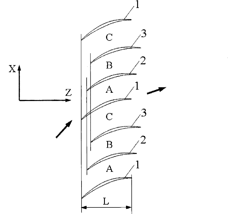
[0024] The arrangement of the cascades in this embodiment is as follows: the front edges of the same row of blades along the tangential direction of the cascade, that is, the X direction, are arranged differently along the axial direction of the cascade, that is, the positions in the Z direction. For each blade group, taking the axial position of the leading edge of the first blade 1 as the axial positioning reference, the second adjacent blade 2 is located on the side of the back surface of the first blade, and its leading edge position Relative to the positioning reference, move back a certain distance along the axial direction of the cascade, and the moved distance is 11% of the axial chord length L of the first blade 1; the third blade 3 adjacent to the second blade 2 is located at On the side of the back surface of the second blade 2, its leading edge moves back a certain distance relative to the leading edge of the second blade 2 along the axial direction of the cascade, ...

Embodiment 2

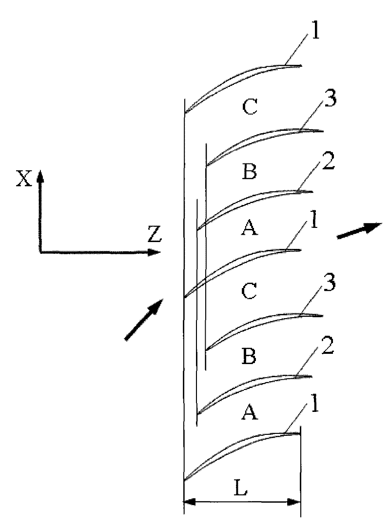
[0028]The arrangement of the cascade in this embodiment is as follows: the front edges of the same row of blades along the tangential direction of the cascade, that is, the X direction, are arranged differently in the front and rear of the cascade axial direction, that is, the Z direction. For each blade group, taking the axial position of the leading edge of the first blade 1 as the axial positioning reference, the second adjacent blade 2 is located on the side of the back surface of the first blade, and its leading edge position Relative to the positioning reference, move back a certain distance along the axial direction of the cascade, and the moved distance is 7% of the axial chord length L of the first blade 1; the third blade 3 adjacent to the second blade 2 is located at On the side of the back surface of the second blade 2, its leading edge moves back a certain distance relative to the leading edge of the second blade 2 along the axial direction of the cascade, and the ...

Embodiment 3

[0030] The arrangement of the cascade in this embodiment is as follows: the front edges of the same row of blades along the tangential direction of the cascade, that is, the X direction, are arranged differently in the front and rear of the cascade axial direction, that is, the Z direction. For each blade group, taking the axial position of the leading edge of the first blade 1 as the axial positioning reference, the second adjacent blade 2 is located on the side of the back surface of the first blade, and its leading edge position Relative to the positioning reference, move back a certain distance along the axial direction of the cascade, and the moved distance is 7% of the axial chord length L of the first blade 1; the third blade 3 adjacent to the second blade 2 is located at On the side of the back surface of the second blade 2, its leading edge moves back a certain distance relative to the leading edge of the second blade 2 along the axial direction of the cascade, and the...


PUM


Abstract

The invention relates to a compressor cascade layout for improving the pneumatic load of blades. Every adjacent three blades in the same blade row form a group, the axial position of the front edge of the first blade (1) is taken as a positioning reference, the second blade (2) adjacent to the first blade is positioned on one side of the surface of the blade back of the first blade, the front edge of the second blade moves backwards along the axial direction of a cascade, and the moving distance is 7 to 15 percent of the axial chord length L of the first blade; the third blade (3) adjacent tothe second blade is positioned on one side of the surface of the blade back of the second blade, the front edge of the third blade moves backwards relatively to the front edge of the second blade along the axial direction of the cascade, and the moving distance is 5 to 15 percent of the axial chord length of the first blade; and the third blade rotates around the front edge of the third blade by 1 to 4 degrees. In the compressor cascade layout, three different airflow channels form in the same blade row, the air flow has unique characteristics different from the prior art, so that the pneumatic load of the blade under the condition that the designed curvature of the blade is unchanged can be effectively improved and the pneumatic stability of the compressor is improved to a certain extent.

Description

1. Technical field [0001] The invention relates to the field of axial-flow impeller machinery, and relates to a compressor cascade layout for improving the aerodynamic load of blades. 2. Background technology [0002] Improving the aerodynamic load of the axial flow compressor is the requirement of the modern high thrust-to-weight ratio aviation gas turbine engine for the compressor. However, generally speaking, increasing the aerodynamic load on the compressor blades often leads to a decrease in the aerodynamic stability of the compressor. For this reason, people have taken many measures in aerodynamic design and structural design to improve the aerodynamic stability of the compressor. The existing conventional axial flow compressor blades adopt a completely axisymmetric and evenly distributed design scheme. When the inlet airflow angle of attack is large, the airflow boundary layer on the back surface of each blade will be separated at the same time, causing rotation in ...

Claims


Application Information

Patent Timeline
Patent Type & Authority Patents(China)
IPC IPC(8): F04D29/34
Inventor 刘前智廖明夫王俨剀王四季杨伸记
Owner NORTHWESTERN POLYTECHNICAL UNIV
Why Eureka
Try Eureka