a centrifugal blower

A technology of centrifugal blower and symmetrical curved surface, which is applied in the direction of mechanical equipment, machine/engine, liquid fuel engine, etc., can solve the problems of low aerodynamic efficiency, low aerodynamic load, high noise, etc., and achieve high aerodynamic efficiency, high aerodynamic efficiency, high The effect of air intake efficiency

Inactive Publication Date: 2020-08-07
江苏乘帆压缩机有限公司
View PDF7 Cites 0 Cited by
  • Summary
  • Abstract
  • Description
  • Claims
  • Application Information

AI Technical Summary

Problems solved by technology

In order to meet the performance requirements of its application in various fields, people usually design the impeller blades into three types: backward, forward and radial. Among them, the bending direction of the backward blade is the same as the trajectory of the gas. High efficiency and low noise, but low aerodynamic load; the bending direction of the forward blade is opposite to the trajectory of the gas, and the aerodynamic load is high, but because the gas is forcibly changed by the blade, the aerodynamic efficiency is low and the noise is large; The bending direction of the impeller blades is perpendicular to the trajectory of the gas, and its related performance is between the backward blades and the forward blades; it can be seen from the above that the existing impeller blades have their own advantages and disadvantages, and they cannot have high performance at the same time. Aerodynamic efficiency and performance at high aerodynamic loads

Method used


Image

  • a centrifugal blower
  • a centrifugal blower
  • a centrifugal blower

Examples


Embodiment 1

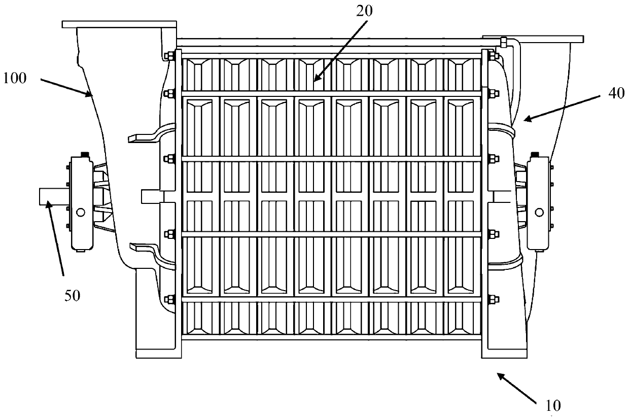
[0045] See figure 1 A centrifugal blower 10 shown includes a rotating main shaft 50 connected to a rotating drive unit (not shown in the figure), an air intake housing 100 integrally installed and connected with the rotating main shaft, and multiple air intake housings installed in the middle housing 20 Stage impeller 30 ( figure 1 impeller not shown) and exhaust casing 40;

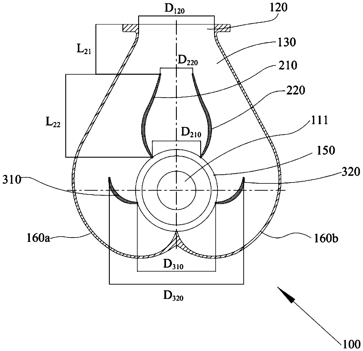
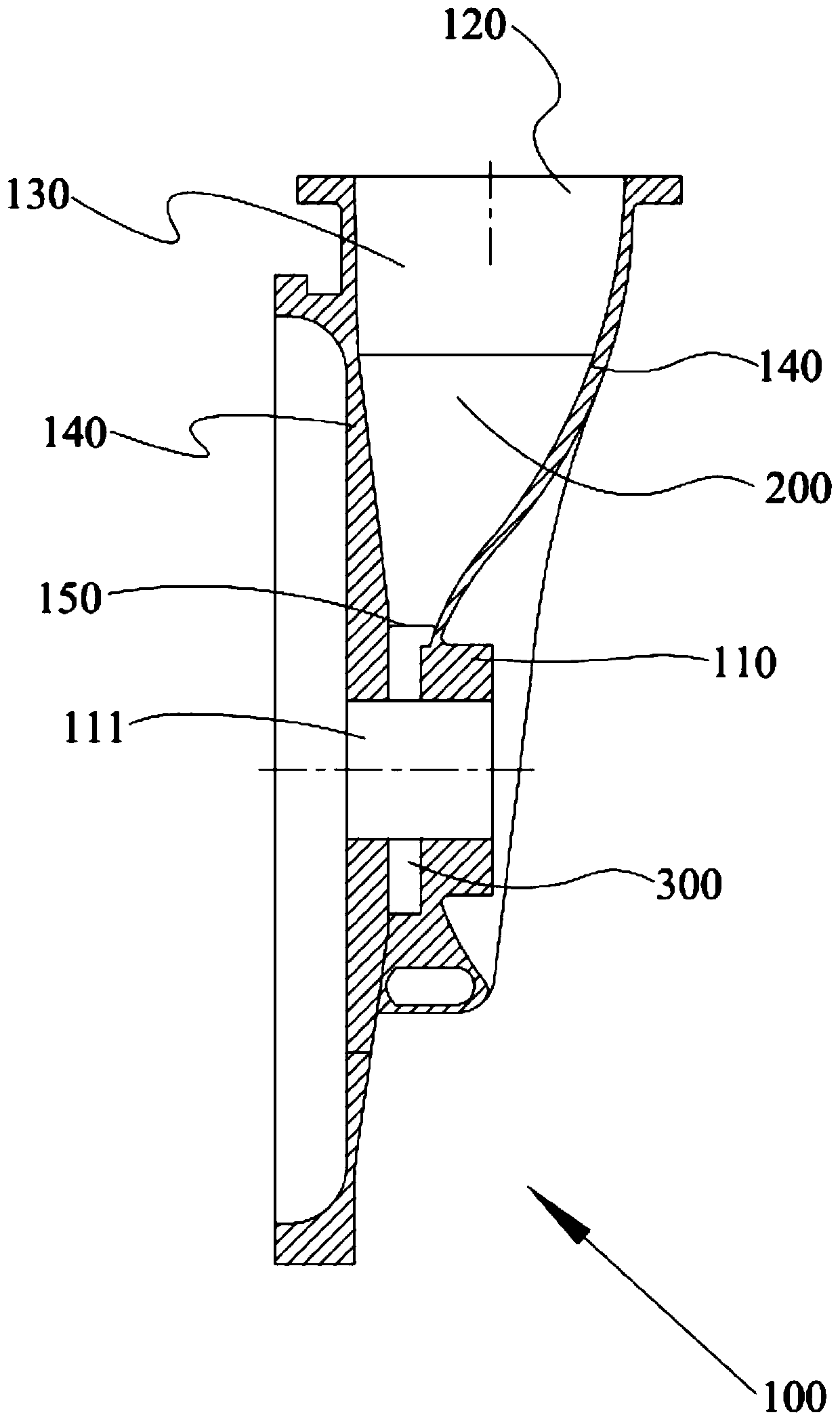
[0046] see further figure 2 and image 3 The air intake casing 100 shown is installed and connected to the main shaft (not shown) of the centrifugal blower through the bearing housing 110 installed with bearings (not shown in the figure), and the air intake casing 100 is provided with an air inlet located above 120 and air intake channel 130, the air inlet 120 communicates with the gas compression unit of the centrifugal blower through the air intake channel 130; the air intake channel 130 is respectively provided with a symmetrical curved surface leading vane group 200 and a symmetrical curved surfac...

Embodiment 2

[0067] The remaining technical solutions of this embodiment 2 are the same as those of the above embodiment 1, the difference is only in the impeller structure, specifically, in this embodiment 2, please refer to Figure 12 and Figure 13 An impeller 30' is shown. The impeller 30' adopts an aluminum alloy integrally cast impeller disc 31' and several blades 32' located on the impeller disc. Each blade 32' is evenly distributed on the inner periphery of the impeller disc 31'. The impeller disc 31' is provided with a rotating shaft hole 33' fixedly connected to the rotating main shaft 50, an axial air inlet 34' communicating with the inlet flow passage, and a radial exhaust outlet 35' communicating with the outlet flow passage; , each vane 32' includes a forward vane section 32a' located at one end near the axial inlet 34' and a rearward vane section 32c' located at one end near the radial exhaust port 35', the forward vane section 32a' and the backward blade section 32c' are c...


PUM


Abstract

The invention discloses a centrifugal blower with efficient aerodynamic efficiency. Symmetrical curved surface main guide blade segments and symmetrical curved surface secondary guide blade segments are arranged in an air intake flow channel of an air intake shell of the centrifugal blower with the efficient aerodynamic efficiency; the symmetrical curved surface main guide blade segments are closeto an air inlet relative to the symmetrical curved surface secondary guide blade segments; guide blade sides of the two sides of the symmetrical curved surface main guide blade segments and the symmetrical curved surface secondary guide blade segments respectively correspond to the shapes of the front inner shell wall and rear inner shell wall of the air intake shell and extend; each blade of animpeller comprises a forward type blade segment located at one end close to an axial air inlet, and a backward type blade segment located at one end close to an radial air outlet; and the forward typeblade segment is connected to the backward type blade segment by a radial blade segment. The structures of the air intake shell and the impeller blades are specially designed, so that the centrifugalblower has multiple technical effects of high intake efficiency, high aerodynamic efficiency, high aerodynamic load and low aerodynamic noise; and finally the centrifugal blower with efficient aerodynamic efficiency is obtained.

Description

technical field [0001] The invention belongs to the field of centrifugal blower product manufacturing, and in particular relates to a centrifugal blower. Background technique [0002] The working principle of the centrifugal blower is mainly to use a number of rotating impellers to do work on the gas, increase the kinetic energy of the gas, and then increase the pressure of the gas through the centrifugal action and the expansion process to achieve a certain air volume and pressure, and then achieve a large flow of high-pressure air supply. technical effect. Centrifugal blowers are widely used in sewage treatment, desulfurization of power plants and other industrial fields because of their good effect of large flow and high pressure air supply. [0003] The centrifugal blower mainly includes core components such as an air intake housing with an air inlet, a rotary drive unit, a gas compression unit composed of a rotating impeller, and an exhaust housing with an exhaust port...

Claims


Application Information

Patent Timeline
Patent Type & Authority Patents(China)
IPC IPC(8): F04D17/12F04D29/42F04D29/44F04D29/22F04D29/24F04D29/66F04D29/051
CPCF04D17/122F04D29/051F04D29/281F04D29/30F04D29/4226F04D29/441F04D29/666F04D29/667
Inventor 宋波雷先华庄贤良
Owner 江苏乘帆压缩机有限公司
Why Eureka
Try Eureka