Honeycomb-shaped laminar flow-plug flow type photocatalytic reactor

A photocatalytic reactor and photocatalytic reaction technology, which are applied in chemical instruments and methods, dispersed particle separation, separation methods, etc. The diameter of the device should not be too large to achieve the effect of facilitating the overall coating, realizing the functions of diversion and air distribution, and reducing the amount of catalyst.

Active Publication Date: 2017-01-04
广州中洲环保科技有限公司
View PDF6 Cites 2 Cited by
  • Summary
  • Abstract
  • Description
  • Claims
  • Application Information

AI Technical Summary

Problems solved by technology

However, in order to ensure the catalysis and sufficient irradiation intensity on the surface, the diameter of the reactor should not be too large, so the gas volume of a single circular reactor is limited
The key point is that if the circular reactors are used in parallel, there must be a gap between the rings, which will increase the difficulty of gas distribution, and the waste gas will be easily discharged directly from the gap without purification, and the space utilization efficiency of the reactor is low and the structure is complex , high cost and other issues limit its practical industrial application

Method used


Image

  • Honeycomb-shaped laminar flow-plug flow type photocatalytic reactor
  • Honeycomb-shaped laminar flow-plug flow type photocatalytic reactor
  • Honeycomb-shaped laminar flow-plug flow type photocatalytic reactor

Examples


Embodiment 1

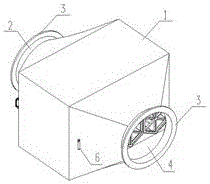
[0036] attached Figure 1-4 The first embodiment of the honeycomb photocatalytic reactor is given. The honeycomb photocatalytic reactor in this embodiment is composed of a rectangular box, an inspection door, a reaction substrate, a lamp tube and its accessories.

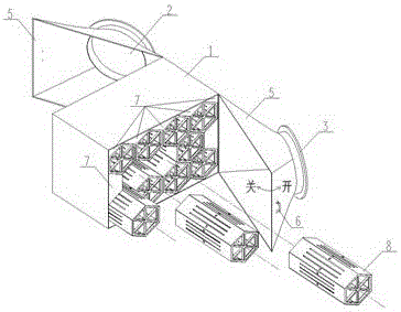
[0037] The box body 1 is used to house the honeycomb-shaped photocatalytic reaction module 8. Inside the box body 1, a plurality of baffles 7 are arranged. pass. The exhaust gas enters the box 1 from the air inlet 2, and after being filtered by the primary filter device (such as non-woven fabric) at the air inlet 2, it enters the honeycomb photocatalytic reaction module 8, and is discharged from the exhaust port 4 after purification. The flanges 3 on the air inlet 2 and the exhaust port 4 are used as reserved interfaces for connecting with the pipelines of the exhaust gas collection system and the exhaust gas discharge system respectively.

[0038] The inlet and outlet ends of the above-mentioned reactor are prov...

Embodiment 2

[0042] attached Figure 5 The second embodiment of the honeycomb photocatalytic reactor is given. The honeycomb photocatalytic reactor in this embodiment is composed of a rectangular box, an inspection door, a reaction substrate, a lamp tube and its accessories.

[0043] In this embodiment, the only access door 5 is located on the top of the box body 1, the maximum opening and closing angle of the access door 5 is 180°, and a bead is provided at the connection between the access door 5 and the box body 1 to ensure airtightness. In order to facilitate direct hoisting from the top, the honeycomb photocatalytic reaction modules 8 are connected by welding in this example.

[0044] Other components and their connections are the same as in Embodiment 1.

Embodiment 3

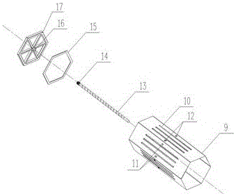
[0046] attached Image 6 The third embodiment of the honeycomb photocatalytic reactor is given. The honeycomb photocatalytic reactor in this embodiment is composed of a box body, an inspection door, a reaction substrate, a lamp tube and its accessories.

[0047] In this embodiment, the box body 1 is a circular tubular structure, and its diameter is the same as that of the air duct for collecting the gas to be treated, and flanges 3 are provided on both the air inlet 2 and the exhaust port 4 . The installation method is to install the reactor directly into the collection pipeline as a piece of air pipe, and connect it to the air pipe through the flange 3 of the air inlet and outlet.

[0048] In this example, only one honeycomb-shaped photocatalytic reaction module 8 is placed in the box, and a plurality of reaction modules can also be arranged, and each reaction module is connected by welding.

[0049] When overhauling, the entire reactor can be overhauled after it is removed...


PUM


Abstract

The invention discloses a honeycomb-shaped laminar flow-plug flow type photocatalytic reactor. The reactor comprises a box, an air inlet, an air outlet and a honeycomb-shaped photocatalytic reaction module. The air inlet and the air outlet are formed in the box, and the honeycomb-shaped photocatalytic reaction module is located inside the box and comprises a reaction channel, a line light source, a lamp base, a lamp base support and a clamping groove. The reaction channel is formed by folding a honeycomb-shaped reaction base plate, and the section of the reaction channel is in a regular hexagon shape; the inner wall of the reaction channel is coated with a photocatalyst; the lamp base support is fixed to the two ends of the reaction channel, the lamp base is arranged in the center of the lamp base support, and the line light source is fixed to the lamp base and penetrates through the central axis of the reaction channel. The single honeycomb-shaped photocatalytic reaction module is designed to be of a porous channel structure in a regular hexagon shape, the inner wall of the channel is coated with the catalyst, the line light source is placed in the central axis of the channel, light is distributed evenly, and the utilization rate of the light source and the catalyst is increased.

Description

technical field [0001] The invention relates to the field of exhaust gas and air purification, in particular to a honeycomb laminar flow-push flow photocatalytic reactor. Background technique [0002] Photocatalytic technology is a promising technology for industrial waste gas or air purification. For the practical application of photocatalysis, the rationality of the photocatalytic reactor structure directly affects the effect of photocatalytic purification. At present, the common industrial-grade photocatalytic reactors on the market adopt a box-type structure, and a number of filter screens coated with catalysts are placed perpendicular to the airflow direction, and the ultraviolet lamp is placed between two adjacent filter screens. In this structure, most of the photons emitted by the ultraviolet lamp are not irradiated vertically on the catalyst filter, and a part of the ultraviolet light is irradiated on the area between two adjacent catalyst filters, resulting in a l...

Claims


Application Information

Patent Timeline
Patent Type & Authority Applications(China)
IPC IPC(8): B01D53/88
CPCB01D53/885
Inventor 宋旭林培真冯文浩张甜甜廖裕芬陈志平郑理慎
Owner 广州中洲环保科技有限公司
Why Eureka
Try Eureka