
Keyboard cover rotating mechanism

A technology of a rotating mechanism and a keyboard cover, which is applied to stringed instruments, instruments, etc., can solve the problems of unreasonable structure, inconvenient installation and disassembly, and inconvenience, and achieve the effect of reasonable structure, convenient disassembly and installation, and convenient installation and disassembly.

Inactive Publication Date: 2010-09-29
PEARL RIVER PIANO GROUP
View PDF2 Cites 0 Cited by
  • Summary
  • Abstract
  • Description
  • Claims
  • Application Information

AI Technical Summary

Problems solved by technology

[0002] The existing keyboard cover rotation mechanism has an unreasonable structure. The structure of the rotation mechanism is: a round hole is opened at one end of the rotation rod, and a hinged column is added to the shaft of the rotation rod. One end of the hinged column is inserted into the side arm, and the other end passes through the The round hole of the rotating rod, and one end of the rotating rod is positioned with a bolt, and the rotating rod forms a hinge with the side arm through the rotating rod shaft
Such a rotating mechanism is very inconvenient to install and disassemble: when installing, one end of the rotating rod shaft needs to be planted into the side arm first, and the other end is aligned with the round hole of the rotating rod to pass through, and then tighten the bolt on the rotating rod shaft to Positioning of the rotating rod. When disassembling, the bolts tightened on the shaft of the rotating rod need to be removed first.
Such installation and removal process is not only inconvenient, but also easy to damage and scratch the side arm and front keyboard cover

Method used


Image

  • Keyboard cover rotating mechanism
  • Keyboard cover rotating mechanism
  • Keyboard cover rotating mechanism

Examples


Embodiment Construction

[0021] The present invention will be further described below in conjunction with drawings and embodiments.

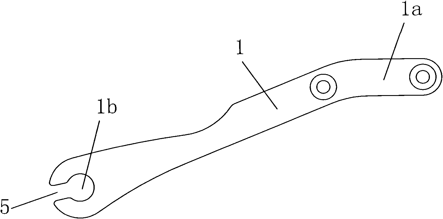
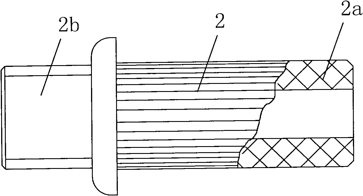
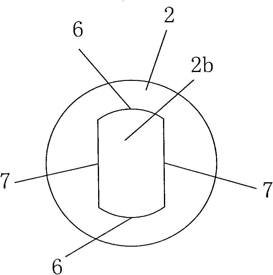
[0022] The keyboard cover rotating mechanism includes a rotating rod 1 and a rotating rod shaft 2, and its structure is as follows: figure 1 , figure 2 , image 3 As shown, one end 2a of the rotating rod shaft 2 is inserted into the side arm 3 of an American piano, the other end of the rotating rod shaft 2 is provided with a convex portion 2b, one end 1a of the rotating rod 1 is fixedly connected with the front keyboard cover 4, and the other end of the rotating rod 1 is provided with a circle The hole 1b and the round hole 1b are provided with a notch 5 corresponding to the shape of the convex part 2b, the convex part 2b enters the round hole 1b through the notch 5, and the rotating rod 1 forms a hinge with the side arm 3 through the rotating rod shaft 2.

[0023] Such as image 3 As shown, the cross section of the convex portion 2 b is composed of four sides, wher...


PUM


Abstract

The invention discloses a keyboard cover rotating mechanism, comprising a rotating bar and a rotating bar shaft, wherein one end of the rotating bar shaft is inserted into a side arm of an American piano and the other end of the rotating bar shaft is provided with a protrusion, one end of the rotating bar is fixedly connected with a front keyboard cover and the other end of the rotating bar is provided with a round hole which is provided with a gap corresponding in shape to the protrusion, the protrusion enters the round hole via the gap, and the rotating bar is articulated with the side arm via the rotating bar shaft.

Description

technical field [0001] The invention relates to a keyboard cover opening and closing device for a piano, in particular to a keyboard cover rotation mechanism. Background technique [0002] The existing keyboard cover rotation mechanism has an unreasonable structure. The structure of the rotation mechanism is: a round hole is opened at one end of the rotation rod, and a hinged column is added to the shaft of the rotation rod. One end of the hinged column is inserted into the side arm, and the other end passes through the The round hole of the turning rod is used, and one end of the turning rod is positioned with a bolt, and the turning rod forms a hinge with the side arm through the turning rod shaft. Such a rotating mechanism is very inconvenient to install and disassemble: when installing, one end of the rotating rod shaft needs to be planted into the side arm first, and the other end is aligned with the round hole of the rotating rod to pass through, and then tighten the b...

Claims


Application Information

Patent Timeline
Patent Type & Authority Applications(China)
IPC IPC(8): G10C3/00G10C3/12
Inventor 黄朝苑潘启槟龚承忠梁剑非
Owner PEARL RIVER PIANO GROUP
Learn More