

Tape cassette
A technology of tape box and retainer, which is applied in the direction of ink ribbon box, printing, printing device, etc., can solve the problem of not being able to obtain good printing results, and achieve the effect of accurate positioning in the upper and lower directions
- Summary
- Abstract
- Description
- Claims
- Application Information
AI Technical Summary
Problems solved by technology
Method used
Image

Examples
no. 1 approach
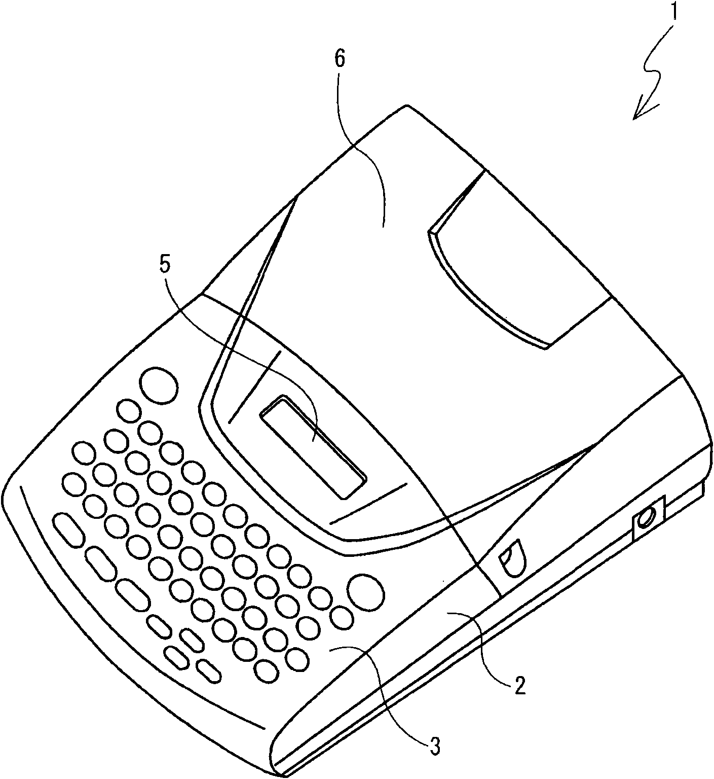
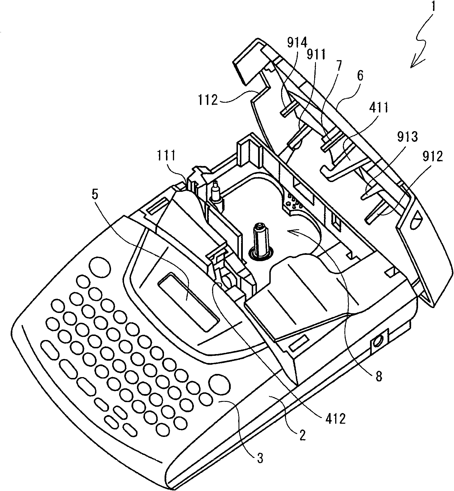
[0108] Reference Figure 1 to Figure 34 The following describes the tape printing device 1 and the tape cassette 30 according to the first embodiment. In the description of this embodiment, the figure 1 and figure 2 Is set as the front side of the tape printing device 1, and figure 1 and figure 2 The upper right side of the is set as the back side of the tape printer 1, and figure 1 and figure 2 Is set to the right side of the tape printer 1, and figure 1 and figure 2 The upper left side of is set to the left side of the tape printing device 1. And will Figure 4 The lower right side is set as the front side of the cassette 30, and Figure 4 The upper left side is set to the rear side of the cassette 30, and the Figure 4 Set the upper right side of the tape box 30 to the right side, set Figure 4 The lower left side of is set to the left side of the tape cassette 30.
[0109] And, used in the following description Figure 4 In etc., in the case where the wall around the casse...
no. 2 approach
[0338] Below, refer to Figure 35 to Figure 38 , The second embodiment will be described. among them, Figure 36 The illustrated tape cassette 30 is a laminated tape cassette with the top case 311 removed. In the first embodiment, in the head holder 74 of the tape printing apparatus 1, two cassette support portions 741 and 742 are provided at two locations on the upstream side and the downstream side of the thermal print head 10. In addition, the tape cassette 30 is provided with supported portions 391 and 392 at two locations adjacent to the head insertion portion 39 corresponding to the cassette support portions 741 and 742. In the second embodiment, the support portion of the tape cassette 30 is provided only on the upstream side of the head holder 74, and the supported portion is provided on the tape cassette 30 only at a location adjacent to the head insertion portion 39 The example is explained. Hereinafter, the description will be focused on the configuration different...
no. 3 approach
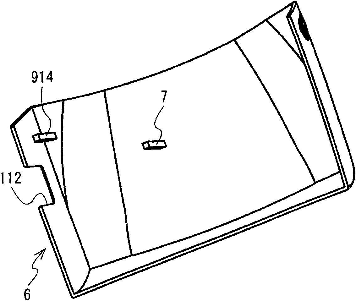
[0350] Below, refer to Figure 39 to Figure 48 , The third embodiment will be described. In the tape cassette 30 of the first and second embodiments described above, the flat portion (first lower flat portion 391B) of the first supported portion 391 supported by the first supporting portion 741 of the head holder 74 is provided in On the bottom shell 312. In the third embodiment, an example in which the flat portion of the first supported portion 391 supported by the first supporting portion 741 is provided on the top case 311 will be described. Among them, the tape printing apparatus 1 of the third embodiment is substantially the same as the first embodiment. However, the cassette cover 6 is not provided with the head pressing member 7 and the peripheral pressing members 911 to 914 provided on the tape printing apparatus 1 of the first embodiment. Hereinafter, the description will be focused on the configuration different from the first embodiment, and the same reference num...
PUM
 Abstract
Description
Claims
Application Information