Temperature self-compensating double grating symmetrical push-pull type fiber grating vibrating sensor

A vibration sensor, fiber grating technology, applied in instruments, measuring devices, measuring ultrasonic/sonic/infrasonic waves, etc., can solve the problems of difficult to meet high-quality measurement of low-frequency vibration signals, no temperature self-compensation, low sensitivity, etc. Stability and adaptability to the environment, elimination of temperature drift, effect of large dynamic range

Active Publication Date: 2010-10-06
NAT UNIV OF DEFENSE TECH
View PDF8 Cites 30 Cited by
  • Summary
  • Abstract
  • Description
  • Claims
  • Application Information

AI Technical Summary

Problems solved by technology

The structure of Wuhan University of Technology is an elastic system composed of steel wire (or steel pipe) and a mass block. Double gratings are used as sensitive elements. After two fiber gratings are welded in series, they are rigidly pasted inside the steel pipe. The signal is too small, the sensitivity is not high, the sensitivity is only 1pm / g, it is difficult to meet the high-quality measurement of low-frequency vibration signals
The structure of Shandong University is an elastic system composed of rubber blocks and mass blocks. Fiber grating sensors are pasted and fixed on three non-corresponding rubber blocks. The six faces of the mass block are respectively connected with a rubber block. Each Dimensionally, a single grating is used as the sensitive element, and it does not have the function of temperature self-compensation

Method used


Image

  • Temperature self-compensating double grating symmetrical push-pull type fiber grating vibrating sensor
  • Temperature self-compensating double grating symmetrical push-pull type fiber grating vibrating sensor
  • Temperature self-compensating double grating symmetrical push-pull type fiber grating vibrating sensor

Examples


Embodiment Construction

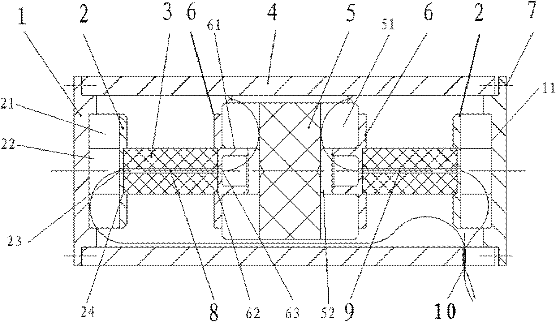
[0026] Such as figure 1 As shown, the present invention consists of a housing, two elastic blocks 3, a mass block 5, a first sensing fiber Bragg grating 8, a second sensing fiber Bragg grating 9, two connecting seats 6 and two supporting bases 2 . The mass block 5 is located between two symmetrical solid elastic body blocks 3, and the two ends of the mass block 5 are pasted with connecting seats 6 respectively. The base 2 is butted and bonded to form a symmetrical push-pull structure, and the two sensing fiber gratings are respectively packaged in the elastomer block 3 to form a dual fiber grating sensor. A modular assembly structure is adopted, and the mass block 5, the elastic body block 3, the first sensing fiber Bragg grating 8, the second sensing fiber Bragg grating 9, the connecting seat 6 and the supporting base 2 form a sensing probe placed inside the housing.

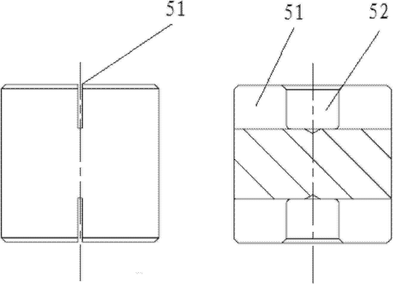
[0027] Such as figure 2 As shown, the mass block 5 is a copper cylinder, and there are first cylindrica...


PUM


Abstract

The invention discloses a temperature self-compensating double grating symmetrical push-pull type fiber grating vibrating sensor. The invention aims to realize a fiber grating vibrating sensor which has the function of temperature self-compensation and has high sensitivity and favorable low-frequency detection performance. The fiber grating vibrating sensor is composed of a shell, two elastic body blocks, a mass block, two sensing fiber Bragg gratings, two connecting seats and two support bases, wherein the mass block is positioned between the two elastic body blocks; the connecting seats are respectively attached to two end faces of the mass block, and respectively abuts against and adheres to one end of each of the two elastic body blocks; and the other end of each of the two elastic body blocks abuts against and adheres to each of the two support bases, thereby constituting a symmetrical push-pull type structure; the positions carved with fiber Bragg gratings on the two fibers are respectively packaged in the two elastic body blocks; and the mass block, the connecting seats, the elastic body blocks, the fiber gratings and the support bases form a sensing probe and are arranged in the shell. The invention can eliminate the effect of temperature drift, has the advantages of high sensitivity, favorable low-frequency detection performance, and can conveniently expand to three dimensions.

Description

technical field [0001] The invention relates to an optical fiber sensor, in particular to an optical fiber grating vibration sensor. Background technique [0002] In the past two decades, fiber Bragg grating (FBG) sensing technology has been extensively and deeply researched and has achieved tremendous development, which can be used to measure strain, temperature, pressure and everything that can be converted into strain, The physical quantity of temperature has been widely used in military and civil fields. FBG acceleration vibration sensing technology has become a new applied research field. In the field of low-frequency vibration sensing applications, FBG acceleration sensors have the advantages of high stability, high precision, low power consumption, good low-frequency characteristics, and strong anti-interference ability, so the application potential is huge. Low-frequency vibration signal detection is used in structural engineering dynamics research (a few tenths of...

Claims


Application Information

Patent Timeline
Patent Type & Authority Applications(China)
IPC IPC(8): G01H9/00
Inventor 孟洲罗洪于洋熊水东王建飞胡永明张学亮胡正良倪明姚琼曹春燕杨华勇张振慧
Owner NAT UNIV OF DEFENSE TECH
Why Eureka
Try Eureka