Check patentability & draft patents in minutes with Patsnap Eureka AI!

Anti-electromagnetic interference ultrasonic probe

An anti-electromagnetic interference and ultrasonic technology, applied in the field of ultrasonic probes, can solve problems such as inaccurate detection signals, and achieve the effect of improving accuracy and accurate detection

Active Publication Date: 2012-03-21
COLIGEN CHINA
View PDF0 Cites 0 Cited by
  • Summary
  • Abstract
  • Description
  • Claims
  • Application Information

AI Technical Summary

Problems solved by technology

[0010] The purpose of the present invention is to solve the technical problems that the existing ultrasonic probes are easily affected by electromagnetic interference signals and the detection signals are inaccurate

Method used


Image

  • Anti-electromagnetic interference ultrasonic probe
  • Anti-electromagnetic interference ultrasonic probe
  • Anti-electromagnetic interference ultrasonic probe

Examples


Embodiment Construction

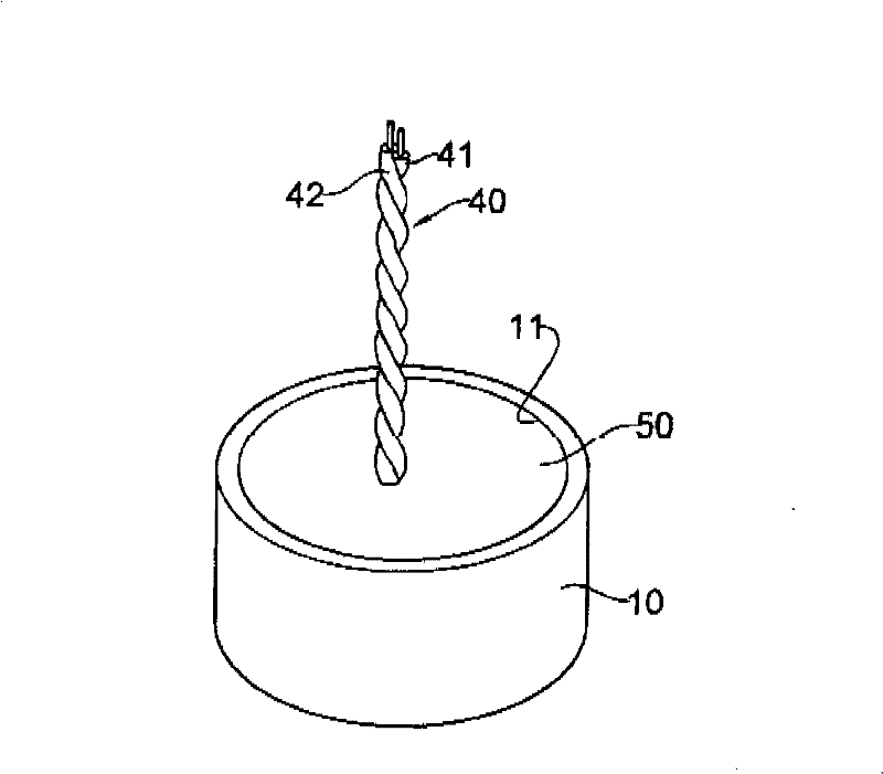
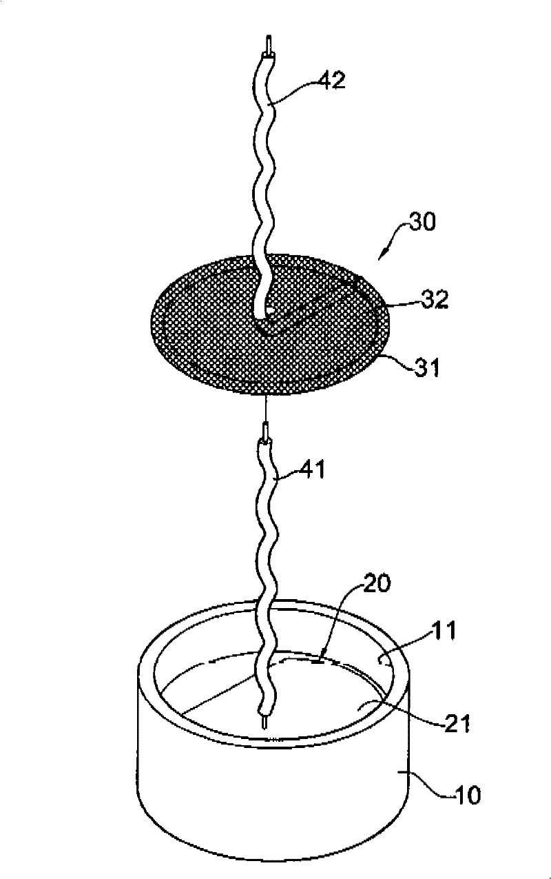
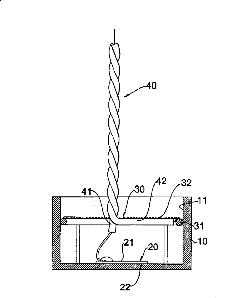
[0031] See first Figure 1 to Figure 4 As shown, the first preferred embodiment of the ultrasonic probe of the present invention includes:

[0032] A metal cover 10 has an opening 11; in this embodiment, the metal cover is a hollow cylinder;

[0033] A piezoelectric ceramic sheet 20 has opposite first and second electrode end faces 21, 22, wherein the first electrode end face 21 faces the opening 11 of the metal cover, and the second electrode end face 22 is disposed on the metal cover 20 Inner bottom surface; in this embodiment, the first electrode end surface 21 is a high potential electrode end surface, and the second electrode end surface 22 is a low potential electrode end surface;

[0034] A metal shielding layer 30 is connected to the metal cover 10, and the metal cover 10 wraps the piezoelectric ceramic sheet 20 therein; in this embodiment, the metal shielding layer 30 is fixed on the inside of the metal cover 10 wall, and is located between the opening 11 of the met...


PUM


Abstract

The invention relates to an anti-electromagnetic interference ultrasonic probe which comprises a metal cover body, a piezoelectric ceramic piece, a metallic shielding layer, a signal line set and sealing glue, wherein a first electrode end surface of the piezoelectric ceramic piece is connected with an inner bottom surface of the metal cover body, and a second electrode end surface thereof is electrically connected with a signal line of the signal line set; the metallic shielding layer is connected with the metal cover body; the piezoelectric ceramic piece is covered inside the metallic shielding layer and the metal cover body; the metallic shielding layer is electrically connected with another signal line of the signal line set; therefore, the second end surface of the piezoelectric ceramic piece can be electrically connected with another signal wire, the metallic shielding layer and the metal cover are electrically connected with one signal, so that an interference electromagnetic signal to be transmitted into the piezoelectric ceramic piece is shielded and isolated, and the piezoelectric ceramic piece is not affected.

Description

technical field [0001] The invention relates to an ultrasonic probe, in particular to an anti-electromagnetic interference ultrasonic probe. Background technique [0002] Ultrasonic probes are widely used, and they are commonly found in the vehicle’s reversing radar device. Since the ultrasonic probe uses piezoelectric ceramics, the reversing radar controller will output an alternating voltage to the piezoelectric ceramics through the signal line group, and the frequency of the alternating voltage When it reaches the ultrasonic range (about 40KHz), the surrounding air will vibrate and emit ultrasonic signals outward. When the ultrasonic signal is reflected by the obstacle and echoes to the piezoelectric ceramic sheet, the piezoelectric ceramic sheet will be vibrated to generate a current, which is transmitted to the controller by the signal line group, and the controller judges the distance of the obstacle according to the magnitude of the current , and then alert the drive...

Claims


Application Information

Patent Timeline
Patent Type & Authority Patents(China)
IPC IPC(8): G01N29/24
Inventor 李世雄
Owner COLIGEN CHINA
Features
  • R&D
  • Intellectual Property
  • Life Sciences
  • Materials
  • Tech Scout
  • Unparalleled Data Quality
  • Higher Quality Content
  • 60% Fewer Hallucinations
Learn More