Device for producing moulded pieces from fibrous material

A technology of fiber materials and molded parts, applied in the field of devices for manufacturing molded parts from fiber materials, which can solve problems such as difficulty in uniform filling of molds, restrictions on the mobility of blowing pipes, etc.

Active Publication Date: 2014-09-10
ROBERT BURKE GMBH
View PDF3 Cites 0 Cited by
  • Summary
  • Abstract
  • Description
  • Claims
  • Application Information

AI Technical Summary

Problems solved by technology

[0004] This method is only suitable for hollow bodies which are open at one end so that the blow-in tube can be arranged there
Furthermore, the mobility of the blow-in tube is very restricted, which makes it difficult to evenly fill the mold
In particular the mold must be rotated during blowing, which leads to additional manufacturing costs

Method used


Image

  • Device for producing moulded pieces from fibrous material
  • Device for producing moulded pieces from fibrous material
  • Device for producing moulded pieces from fibrous material

Examples


Embodiment Construction

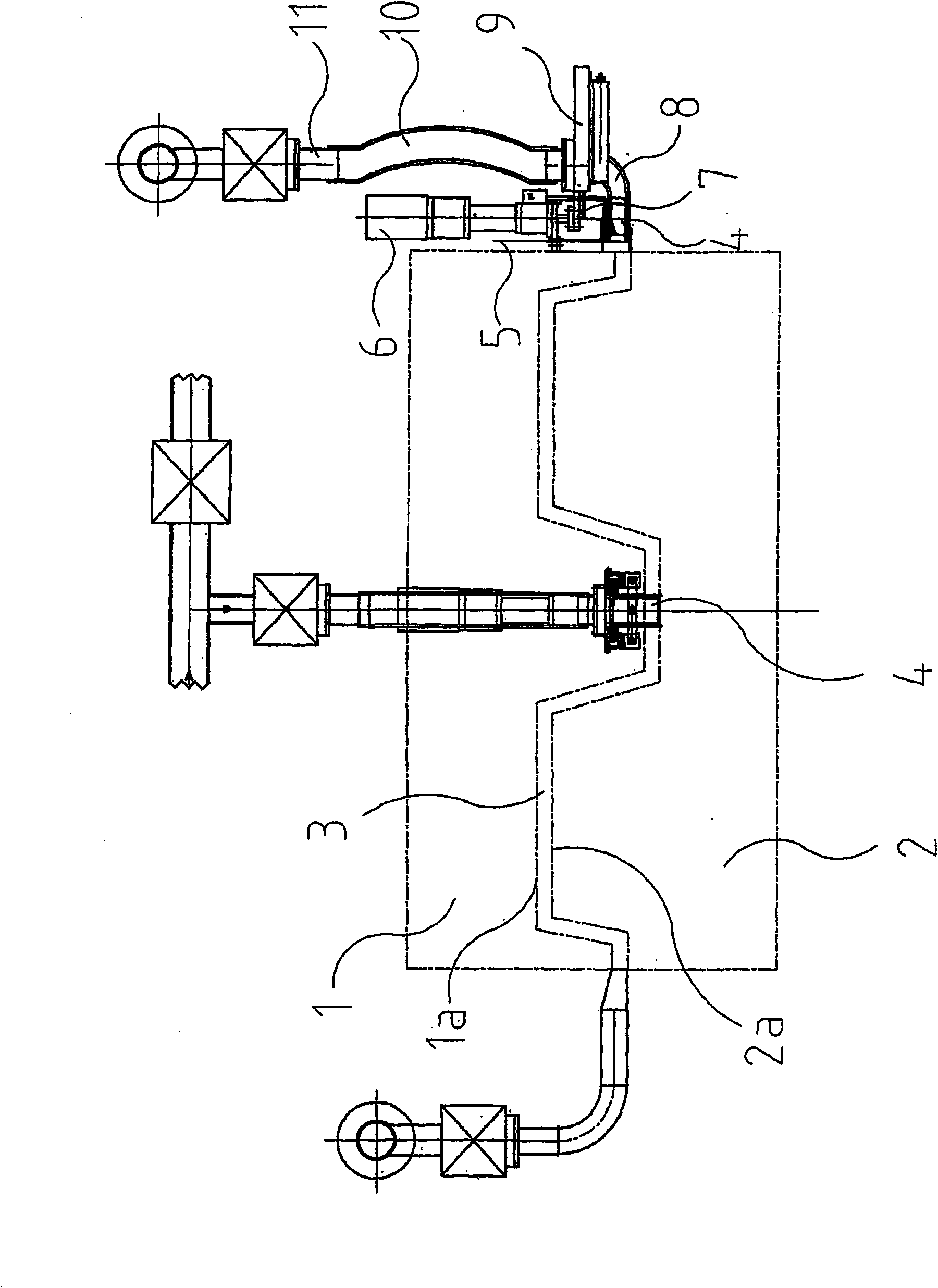
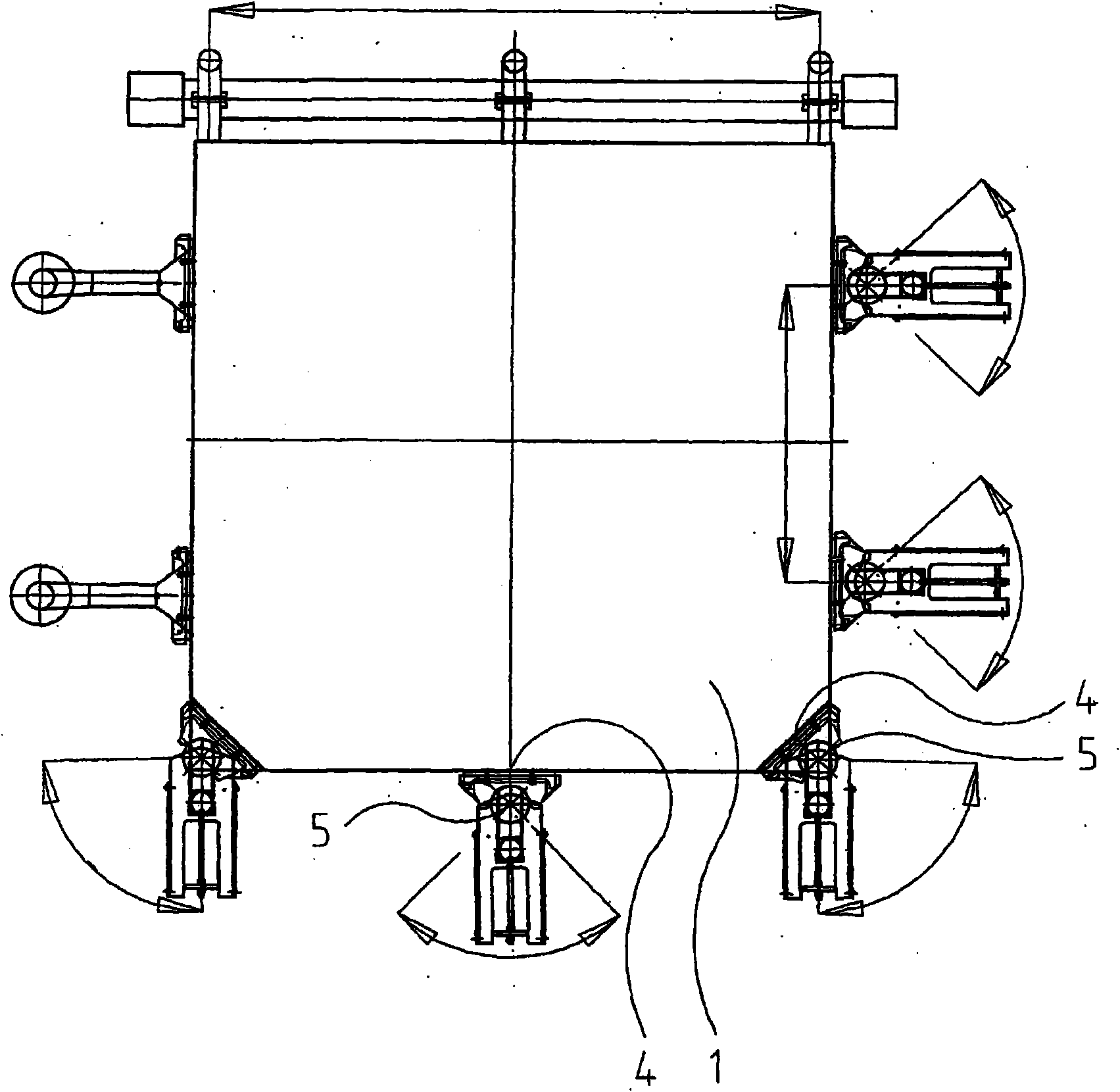
[0033] exist figure 1 In FIG. 2 , a mold can be seen comprising an upper mold 1 and a lower mold 2 assembled such that their inner sides 1 a and 2 a towards each other form a closed intermediate chamber 3 . Said intermediate chamber already defines the contour of the three-dimensional shaped part to be produced; however, it is advantageous that the upper mold 1 and the lower mold 2 are first used to produce a parison, which is then compacted by another upper mold into The final molded part. The insides 1a and 2a of the moulds are generally perforated in a screen-like manner so that the air flow loaded / carrying the synthetic fibres, which flows laterally into the intermediate chamber 3, can escape from the intermediate chamber 3, while the fibers accumulate in the center in the room. In this case, the air permeability of the inner walls 1 a and 2 a can be locally different in order to be able to vary the fiber filling, ie the fiber density, in the intermediate chamber 3 .

...


PUM


Abstract

The invention relates to a device for producing a three-dimensional shaped part (30) from fiber material using a multi-part mold (1, 2), the inside of which mold (1a, 2a) at least partially defines the profile of a molded part, wherein fibers are blown into said mold by an air flow via at least one nozzle (4) and then escape through an opening of said mould, so that said fibers accumulate on the inside of the mould, followed by said The fibers are optionally locally compacted, after which the fibers are bonded to one another by the heat input and finally removed from the mold ( 1 , 2 ) as a molded part ( 30 ). What is important here is that the blowing direction of the nozzles ( 4 , 24 , 34 ) can be swiveled, the swivel axis extending close to the outside of the molded part, the fibers being blown in through a plurality of nozzles activated at different times.

Description

technical field [0001] The invention relates to a device for producing a three-dimensional molded part from fiber material using a multi-part mold, the inside of which at least partially defines the contour of the molded part, wherein the fibers are blown by an air flow via at least one nozzle Blowing into the mold and then escaping through the opening of the mould, so that the fibers accumulate on the inside of the mould, the fibers are then optionally compacted locally, after which the fibers are bonded to each other by the heat input, finally as The molded part is removed from the mold. Background technique [0002] A device of this type is known from DE 10324735. The content of said documents also becomes the subject of the present application in order to avoid repetitions. [0003] Furthermore, it is known from DE 2318501 to produce parisons during the production of hollow bodies from synthetic / plastic fibers, the machining being carried out by means of rotary perfora...

Claims


Application Information

Patent Timeline
Patent Type & Authority Patents(China)
IPC IPC(8): B29B11/16B29C70/30D04H1/00
CPCB29B11/16D04H1/00Y10T428/24124
Inventor M·海因尔
Owner ROBERT BURKE GMBH
Why Eureka
Try Eureka