Shaft coupling

A coupling and shaft sleeve technology, applied in the field of hydraulic machinery, can solve problems such as troubles and increased costs, and achieve the effects of cost saving, convenient installation, and good shock absorption performance

Inactive Publication Date: 2010-10-13
太仓成铭液压机械有限公司
View PDF0 Cites 10 Cited by
  • Summary
  • Abstract
  • Description
  • Claims
  • Application Information

AI Technical Summary

Problems solved by technology

[0002] At present, in the field of hydraulic machinery, most of the elastic bodies of existing couplings are integrally connected. After a cer

Method used


Image

  • Shaft coupling
  • Shaft coupling
  • Shaft coupling

Examples


Embodiment Construction

[0014] The present invention will be further explained below in conjunction with the accompanying drawings and specific embodiments.

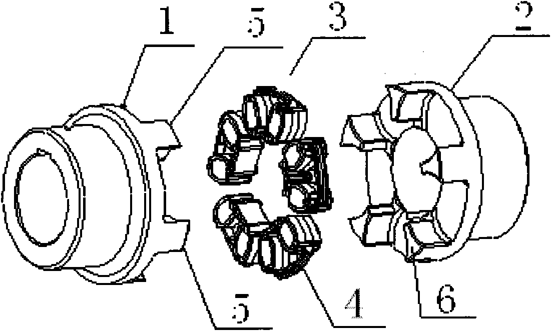
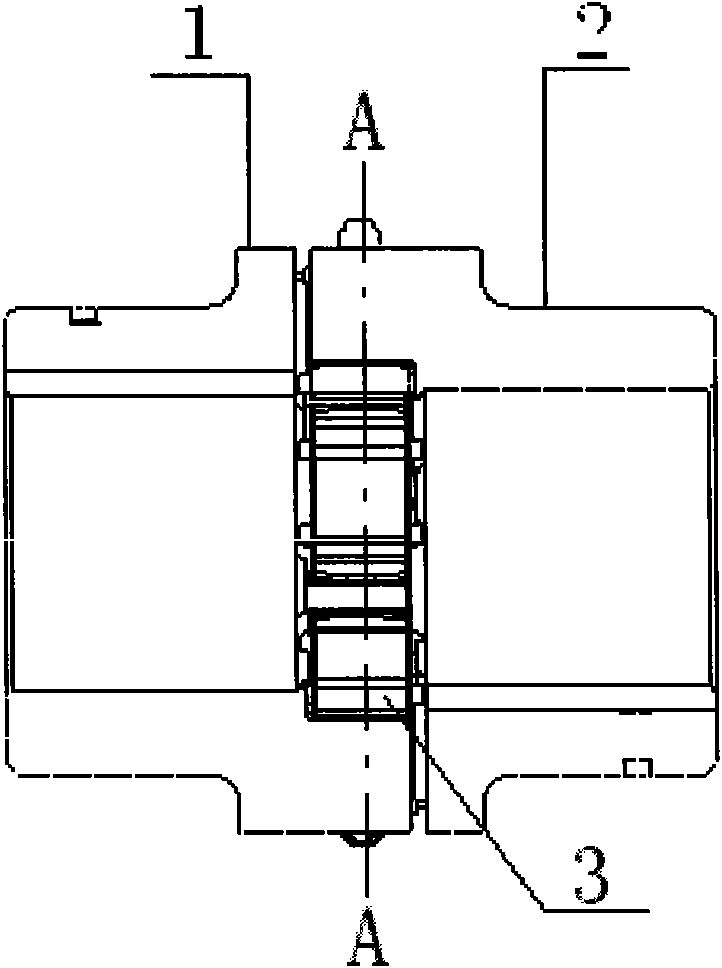
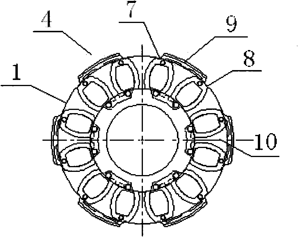
[0015] Such as figure 1 , figure 2 , image 3 with Figure 4 A shaft coupling shown includes a first shaft sleeve 1, a second shaft sleeve 2 and an elastic body 3 installed between the first shaft sleeve 1 and the second shaft sleeve 2, and the elastic body 3 includes 6 elastic elements 4. The elastic element 4 includes a first tooth 7 and a second tooth 8, the first tooth 7 and the second tooth 8 are connected by a rib 9, and a hole is formed between the first tooth 7, the second tooth 8 and the rib 9 10. The hole 10 is matched with the second tooth 6 of the second bushing 2 . The elastic element 4 is detachably installed between two adjacent first teeth 5 of the first bushing 1, and the second bushing 2 is connected to the first bushing 1 and the elastic Body 3 is combined to form a whole.

[0016] When the present invention is in use,...


PUM


Abstract

The invention discloses a shaft coupling, which comprises a first shaft sleeve, a second shaft sleeve and an elastomer arranged between the first shaft sleeve and the second shaft sleeve, wherein the elastomer comprises a plurality of elastic elements, and each elastic element is detachably arranged between the first shaft sleeve and the second shaft sleeve. The shaft coupling is provided with the split-type elastomer, and has convenient installation; the entire elastomer does not need to be replaced after being damaged, and the damaged part only needs to be replaced, so the maintenance is very convenient, and the cost can be saved for customers; in addition, the elastic element arranged between the two adjacent claw-shaped teeth of each shaft sleeve has good vibration reducing performance; and because the elastic element adopts a double tooth structure and is arranged in an axial inserting way, the tight structure can not only transmit torque, but also effectively compensate for installation deviation and absorb vibration and shock load.

Description

technical field [0001] The invention relates to the field of hydraulic machinery, in particular to a shaft coupling. Background technique [0002] At present, in the field of hydraulic machinery, most of the elastic bodies of existing couplings are integrally connected. After a certain claw of the elastic body is damaged, the entire set of elastic bodies must be replaced, which is very troublesome and increases the cost. Contents of the invention [0003] Purpose of the invention: The purpose of the invention is to solve the deficiencies of the prior art and provide a coupling with a split detachable elastic body installed. [0004] Technical solution: In order to achieve the above purpose, a shaft coupling according to the present invention includes a first shaft sleeve, a second shaft sleeve and an elastic body installed between the first shaft sleeve and the second shaft sleeve. The elastic body includes a plurality of elastic elements, and each elastic element is deta...

Claims


Application Information

Patent Timeline
IPC IPC(8): F16D3/12
Inventor 肖聪吴家宝
Owner 太仓成铭液压机械有限公司
Why Eureka
Try Eureka