
Intelligent double-brightness impression LED lamp

A technology of LED lamps and brightness sensing, which is applied in the direction of electric lamp circuit layout, energy-saving control technology, lighting and heating equipment, etc., and can solve problems such as lighting effects in difficult corridors

Active Publication Date: 2010-10-13
HEBEI DAOPU OPTOELECTRONICS TECH CO LTD
View PDF0 Cites 11 Cited by
  • Summary
  • Abstract
  • Description
  • Claims
  • Application Information

AI Technical Summary

Problems solved by technology

[0003] Although this lighting circuit can realize the function of "lights on when people come, lights off when people leave", there are the following defects in the use process: First, because there is only one controllable lighting source in the circuit, when no one enters the corridor Corridors or when failing to approach the effective range of the sound sensing element 2 (generally only 2 or 3 meters) the corridor will be in a dark state, people will have a sense of fear in it, and it is difficult to achieve an ideal corridor lighting effect; If the sensor element is used as the control signal, it is difficult to overcome the interference of surrounding noises such as cars, lightning, firecrackers, etc. on the above circuit

Method used


Image

  • Intelligent double-brightness impression LED lamp
  • Intelligent double-brightness impression LED lamp
  • Intelligent double-brightness impression LED lamp

Examples


Embodiment Construction

[0016] The circuit and circuit principle of the intelligent dual-brightness sensing LED lamp provided by the present invention will be further described in detail below in conjunction with the accompanying drawings.

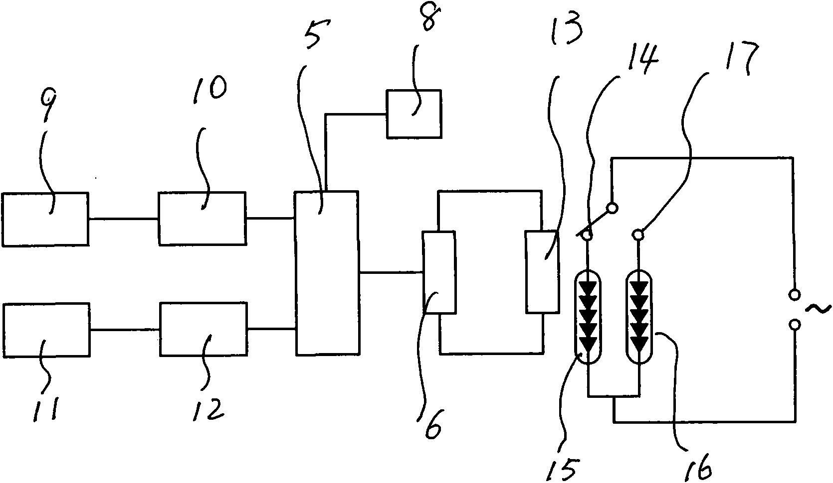
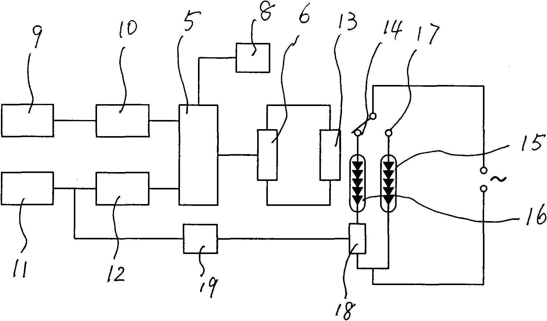
[0017] Such as figure 2 Shown is the circuit block principle diagram of the dual-brightness sensing LED lamp controlled by human body infrared and natural light provided by the present invention. The circuit constituting the intelligent dual-brightness sensing LED lamp includes: a light sensing circuit composed of a light sensing element 11 and a photoelectric signal circuit 12 connected thereto, a human body infrared sensing element 9 and an infrared electric signal amplification circuit connected thereto The infrared sensor circuit that the circuit 10 forms and the delay switch circuit 8 are respectively connected with the input end of the three-state AND gate 5 to form a state selection circuit; the output end of the AND gate is connected with the trigger end...


PUM


Abstract

The invention belongs to the technical field of lamps, in particular to an intelligent double-brightness impression LED lamp. The technical scheme for forming the intelligent double-brightness impression LED lamp is that: the LED lamp comprises a state selection circuit, an electromagnetic relay control circuit, a circuit loop, and a time-delay circuit, wherein the state selection circuit is formed by connecting an optical sensing circuit and a second sensing circuit with an input end of an AND gate circuit respectively; the electromagnetic relay control circuit is formed by connecting an AND gate input end with a triggering end for controlling a trigger switch of an electromagnetic relay coil; the circuit loop is formed by connecting a normally open contact and a normally closed contact of the electromagnetic relay with an auxiliary luminous element and a main luminous element respectively; and the time-delay circuit for controlling the main luminous element is formed by connecting a time-delay switch circuit with an input end of the AND gate circuit or the triggering end of the trigger switch. Due to the arrangement of a main light source and an auxiliary light source formed by LED lamps, after the double-brightness impression LED lamp is arranged on the staircase of a corridor, the auxiliary light source is positioned in a normally bright state, and the main light source realizes the function that people come with the light on and go with the light off. Meanwhile, the double-brightness impression LED lamp also can eliminate the fear in the darkness in the corridor, and is an ideal illumination lamp in the corridor.

Description

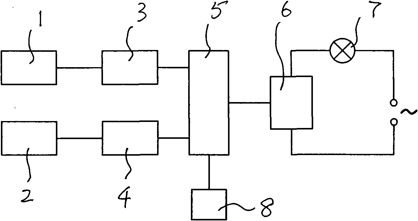
technical field [0001] The invention belongs to the technical field of lamps, and in particular relates to an intelligent dual-brightness induction LED lamp capable of realizing natural light and human induction conversion control. Background technique [0002] At present, the lighting of corridors and stairs generally adopts incandescent lamps, fluorescent lamps or energy-saving lamps or LED lamp lighting circuits controlled by a delay switch circuit controlled by sound and light. The circuit principle of the lamp is as follows figure 1 As shown, it includes a light sensing element 1 and a sound sensing element 2, and the two sensing elements are respectively connected to the three input terminals of the AND gate circuit 5 through the signal amplifying units 3 and 4 and the lighting delay control circuit. The output end of the AND gate is connected with the trigger end of the trigger switch 6 of the controlled lighting circuit 7 . Its working principle is: during the day,...

Claims


Application Information

Patent Timeline
Patent Type & Authority Applications(China)
IPC IPC(8): F21S8/00F21V23/00H05B37/02F21Y101/02
CPCY02B20/48Y02B20/40
Inventor 乔光辉吴军亮赵纯
Owner HEBEI DAOPU OPTOELECTRONICS TECH CO LTD
Learn More