Method for aging of low-voltage, high-current and non-isolated DC-DC power supply

A non-isolated, power aging technology, applied in power supply testing and other directions, can solve the problems of thermal design difficulties, low efficiency, and large heat generation of energy-saving electronic loads, and achieve the effect of filling the gap in the industry and achieving good energy-saving effect.

Inactive Publication Date: 2010-10-20
DONGGUAN GUANJIA ELECTRONICS EQUIP
View PDF3 Cites 20 Cited by
  • Summary
  • Abstract
  • Description
  • Claims
  • Application Information

AI Technical Summary

Problems solved by technology

This aging method has a good energy-saving effect on the general DC-DC power supply, but the DC-DC power supply used for aging test low-voltage and high-current output has the following disadvantages: (1) The aging test system is generally divided into product area and load area, The aging power supply is placed in the product area, and the energy-saving electronic load is placed in the load area, which is convenient for independent control of the temperature of the product area and the load area, so the output terminal of the product and the input terminal of the electronic load need to be connected through a transfer connector, and Need a longer piece of wire
(2) The input voltage of the energy-saving electronic load is very low, and the input current is very large. The efficiency of such an energy-saving electronic load is often only about 50%, and the other 50% of the energy will be consumed in

Method used


Image

  • Method for aging of low-voltage, high-current and non-isolated DC-DC power supply
  • Method for aging of low-voltage, high-current and non-isolated DC-DC power supply
  • Method for aging of low-voltage, high-current and non-isolated DC-DC power supply

Examples


Embodiment Construction

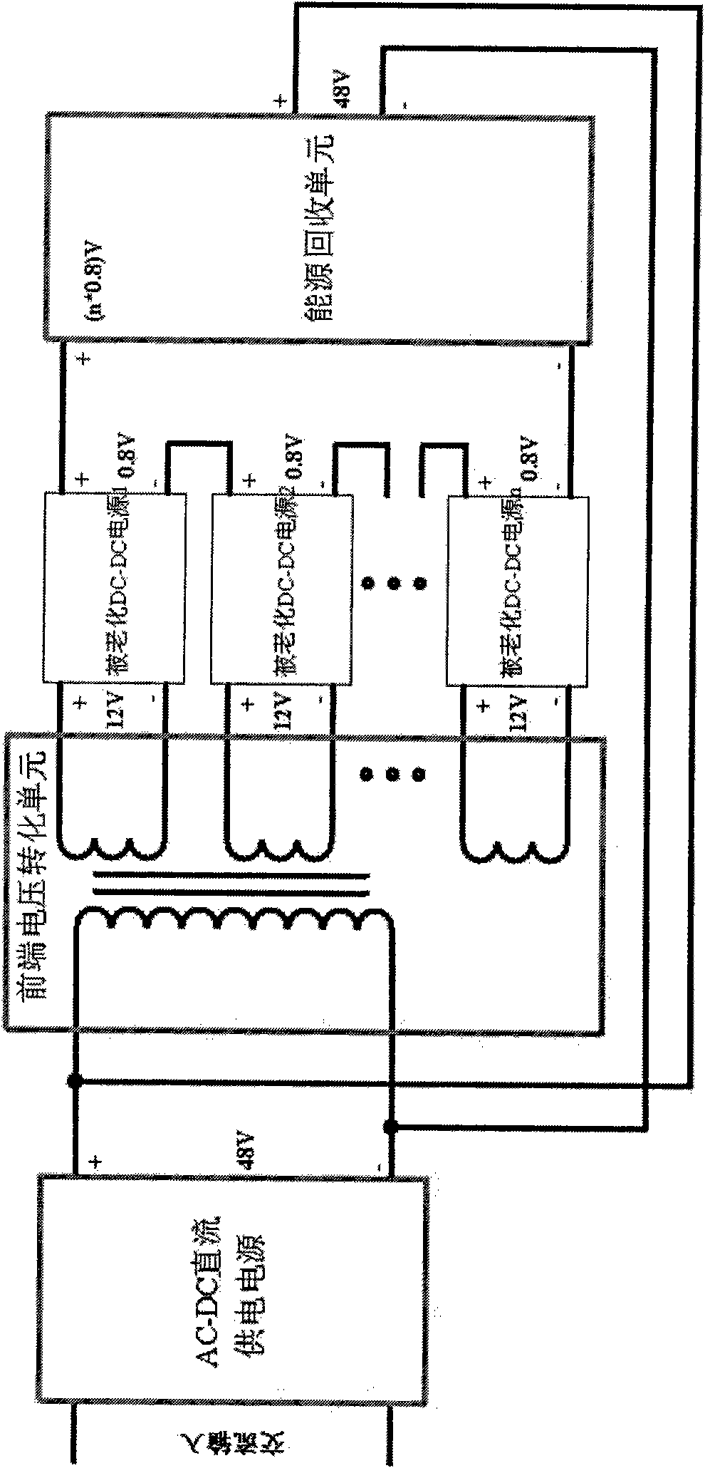
[0016] See image 3 Shown: the low-voltage high-current non-isolated DC-DC power supply aging method of the present invention is to set the front-end voltage conversion unit at the output end of the AC-DC DC power supply, and convert the DC voltage of 48V output by the AC-DC DC power supply to Multiple output voltages that are electrically isolated from it, the multiple output voltages are respectively connected to the input terminals of multiple aged DC-DC power supplies, and the voltage obtained after connecting the output voltages of the aged DC-DC power supplies in series is converted to 48V by the energy recovery unit output, and connected to the input of the front-end voltage conversion unit.

[0017] See Figure 4 Shown: the front-end voltage conversion unit converts the DC 48V voltage output by the AC-DC DC power supply into multiple DC 12V voltage outputs that are electrically isolated from it. This circuit adopts a double-terminal forward topology, and the output v...


PUM


Abstract

The invention discloses a method for aging of a low-voltage, high-current and non-isolated DC-DC power supply. In the method, the output end of an AC-DC direct-current power supply is provided with a front-end voltage conversion unit which is used for converting the DC voltage output by the AC-DC direct-current power supply into a plurality of output voltages electrically isolated from the DC voltage output by the AC-DC direct-current power supply, the output voltages are respectively connected with the input ends of a plurality of aging DC-DC power supplies, the voltage obtained through serial connection of the output voltages of the aging DC-DC power supplies is converted into a DC voltage output identical to the DC voltage output of the AC-DC direct-current power supply through an energy recovery unit and is then connected to the input end of the front-end voltage conversion unit. Due to the combination of the front-end voltage conversion unit, the aging power supplies and the energy recovery unit, the invention realizes the high-efficiency aging test for the non-isolated DC-DC power supply with a low output voltage and a high output current, and can recycle more than 80 percent of the output power of the aging power supplies, thereby achieving good energy-saving effect, and filling the gap in the industry.

Description

Technical field: [0001] The invention relates to the technical field of energy-saving electronic products, in particular to energy-saving aging test equipment for non-isolated DC-DC power supplies that output low voltage and high current. Background technique: [0002] The traditional switching power supply aging test method is to use a high-power resistor as a load for aging testing, which is a huge waste of electric energy. In recent years, some patent technical documents have appeared, proposing to replace energy-consuming resistive loads with energy-saving electronic loads, and to feed back electric energy to the input end of the aging switching power supply while achieving the purpose of on-load aging testing, so as to save electric energy. [0003] Chinese patent CN 200510062317.9 discloses a power aging system, see figure 1 Shown: The aging system uses AC-DC DC power supply to supply power to all aging DC-DC power supplies, the output of each aging power supply is co...

Claims


Application Information

Patent Timeline
IPC IPC(8): G01R31/40
Inventor 王俊邹曙
Owner DONGGUAN GUANJIA ELECTRONICS EQUIP
Why Eureka
Try Eureka