

Method of sintering low temperature waste heat circulation and discharged waste gas reduction and device thereof
A low-temperature waste heat and waste gas technology, which is applied in waste heat treatment, lighting and heating equipment, furnaces, etc., can solve the problems that waste heat utilization of waste gas is not involved, and the waste heat utilization rate of sintering process is less than 30%, which is beneficial to environmental protection and reduces solid waste. Effects of fuel consumption, load reduction and temperature
- Summary
- Abstract
- Description
- Claims
- Application Information
AI Technical Summary
Problems solved by technology
Method used
Image

Examples
Embodiment 1
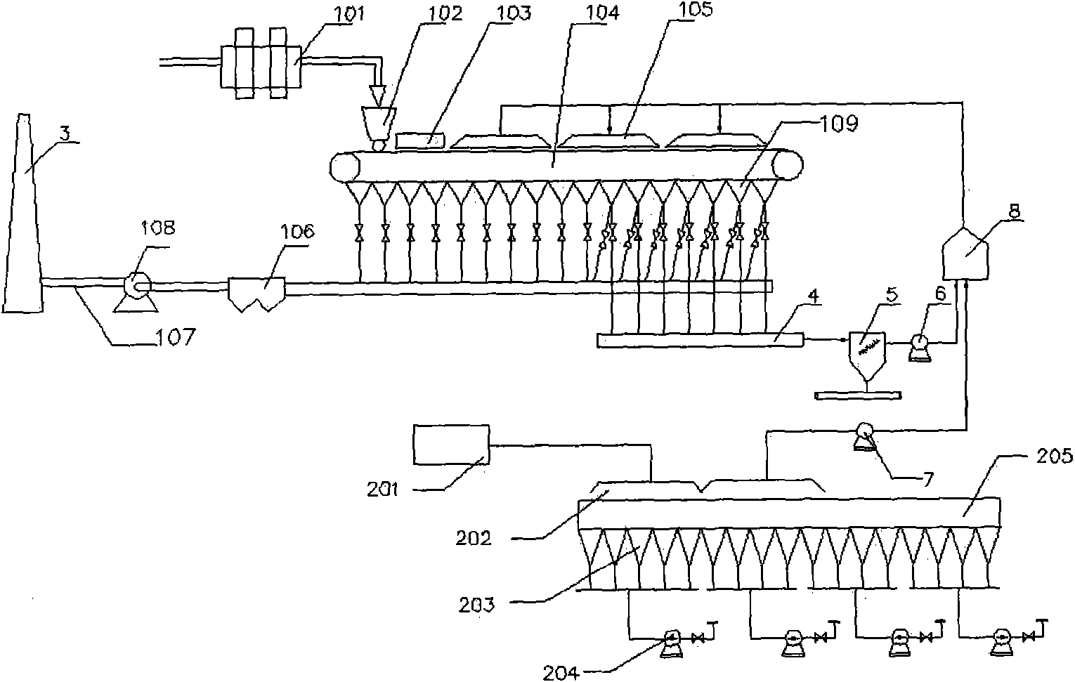
[0038] Such as figure 1 As shown, the area of a station is 132m 2 On the sintering machine, (the sintering machine is equipped with a main exhaust fan, the main exhaust gas volume is 469390Nm 3 / h), the higher temperature flue gas (100~450°C, 100000Nm 3 / h) Extracted from the high-temperature flue 4, returned by the dust collector 5 and the flue gas fan 6, and extracted by the exhaust fan 7 from the hot exhaust gas (300000Nm 3 / h, above 150°C) enters the mixer 8 for mixing, then enters the sintering machine hood 105 of the sintering machine, and sends it to the surface of the material layer of the sintering machine to realize waste gas circulation sintering.
[0039] The flue gas volume of the sintering machine air box at the tail of the sintering machine is all the flue gas in the tail air box with a flue gas temperature exceeding 100 °C, that is, all the exhaust gas with a flue gas temperature greater than 100 °C is circulated, and its flue gas volume accounts for about ...
Embodiment 2
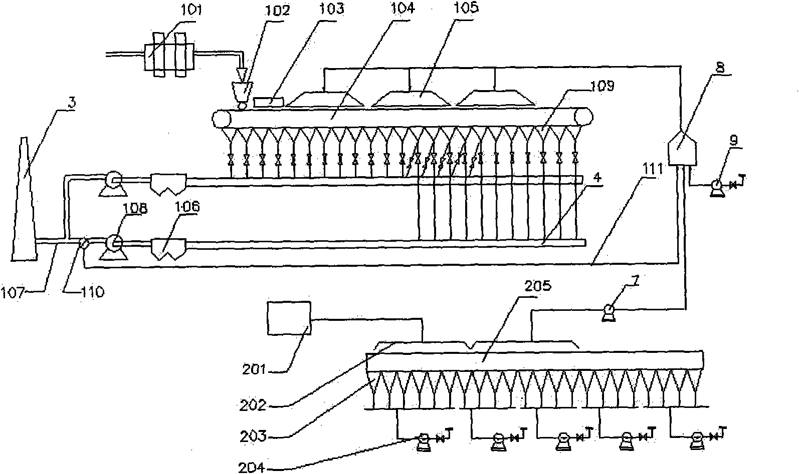
[0043] Such as figure 2 As shown, in an area of 450m 2 On the sintering machine, (the sintering machine is equipped with 2 main exhaust fans, and the flue gas volume of each fan is 21000m 3 / min), the flue gas with high temperature in the wind box 109 at the tail of the sintering machine is concentrated into a large flue, that is, it is extracted from the high-temperature flue 4, and is drawn back through the electrostatic precipitator 106 and the main exhaust fan 108 of the sintering machine. After passing through the valve 110, through the return pipeline 111, the three streams of gas that are extracted from the oxygen supply fan 9 and the hot exhaust gas from the annular cooler through the exhaust fan 7 enter the mixer 8 for mixing, and then enter the sintering machine. Inside the sintering machine air cover 105, it is sent to the surface of the material layer of the sintering machine to realize the waste gas circulation and sintering. Utilizing the three-way valve 110...
Embodiment 3
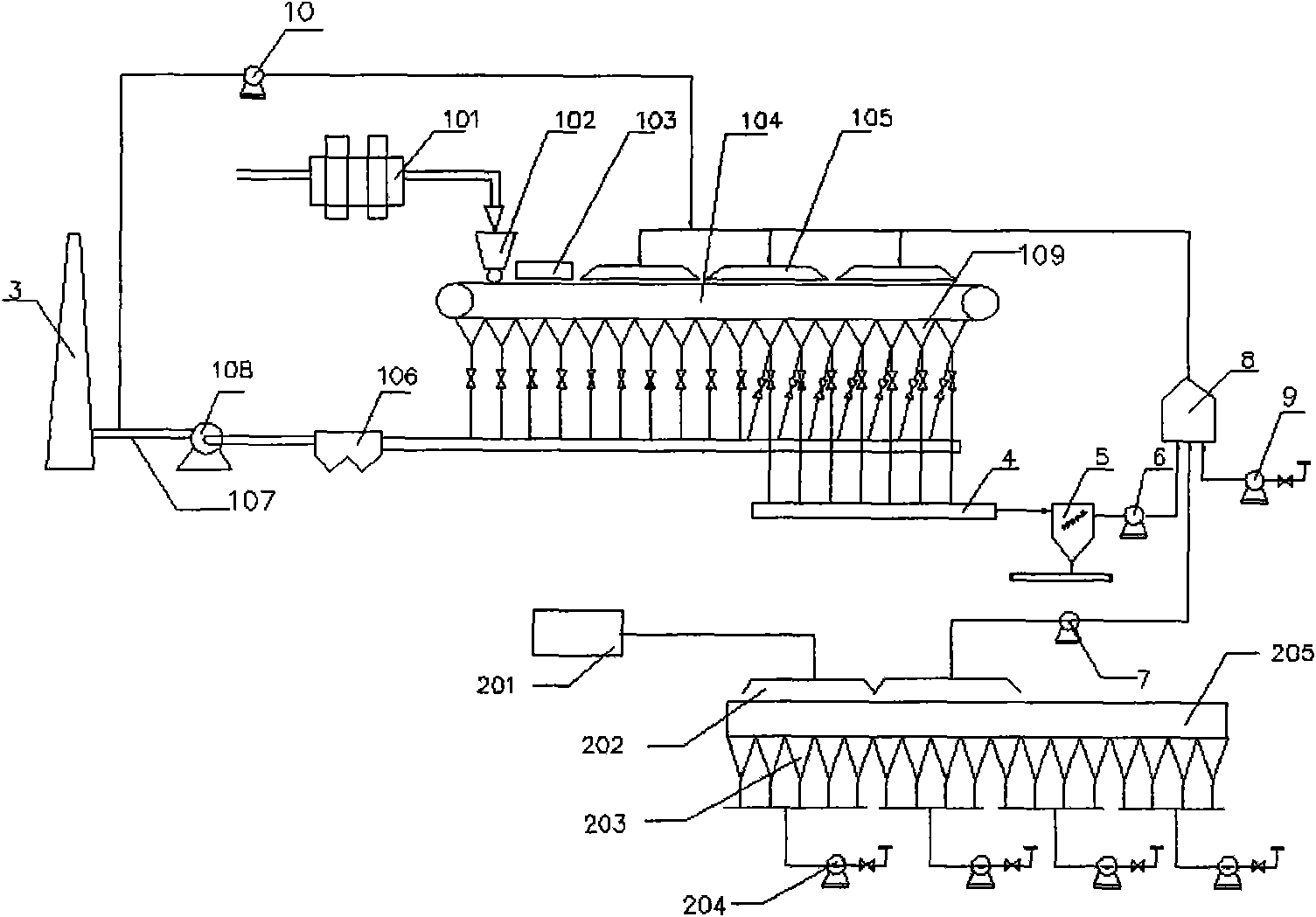
[0047] Such as image 3 As shown, the area of a station is 132m 2 On the sintering machine (the system is equipped with a main exhaust fan), a part of the flue gas is extracted from the exhaust flue 107 connected to the chimney 3 through the auxiliary circulation fan 10, enters the sintering machine hood 105 of the sintering machine, and is sent to the sintering machine. The surface of the machine material layer forms an auxiliary circulation pipeline.
[0048] The higher-temperature flue gas at the tail of the bellows 109 of the sintering machine is extracted from the high-temperature flue 4, and is guided back through the dust collector 5 and the flue gas fan 6, and the oxygen is extracted through the oxygen supply fan 9, and the exhaust gas fan 7 is extracted from the ring type. The three streams of hot waste gas from the cooling machine enter the mixer 8 for mixing, then enter the sintering machine hood 105 of the sintering machine, and send them to the surface of the m...
PUM
 Abstract
Description
Claims
Application Information