Vehicle transfer

A transfer case and vehicle technology, which is applied to vehicle components, control devices, transportation and packaging, etc., can solve problems such as difficult driving, complicated and troublesome operation of the driver, and achieve the effect of improving driving performance

Inactive Publication Date: 2010-11-03
TOYOTA JIDOSHA KK
View PDF7 Cites 10 Cited by
  • Summary
  • Abstract
  • Description
  • Claims
  • Application Information

AI Technical Summary

Problems solved by technology

However, in this case, the driver performs complicated and troublesome operations, making it difficult to drive smoothly on various road surfaces

Method used


Image

  • Vehicle transfer
  • Vehicle transfer
  • Vehicle transfer

Examples


Embodiment Construction

[0123] The following will refer to Figures 1 to 12 Embodiments of the present invention are described in detail.

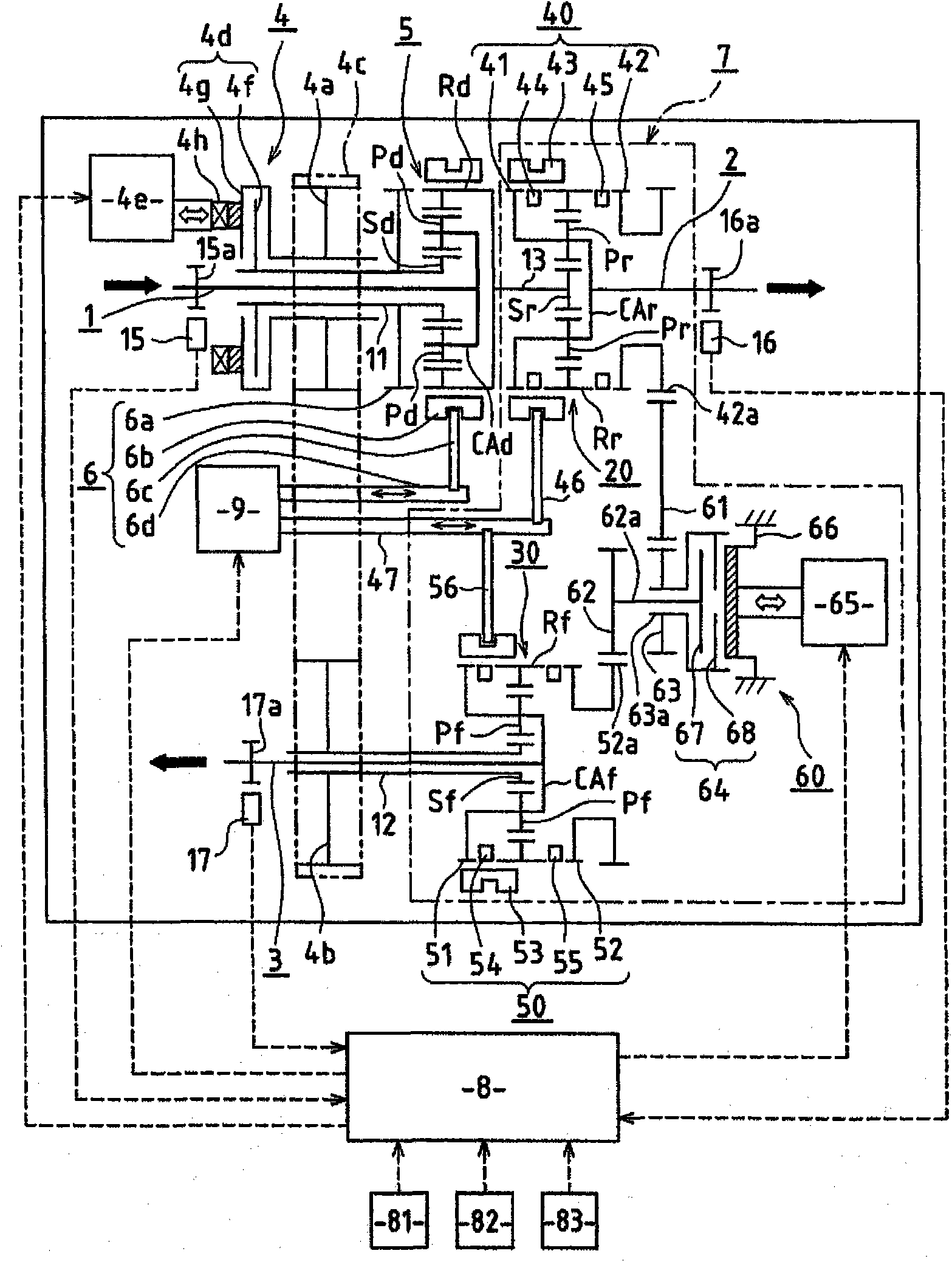
[0124] First, in Figures 1 to 10 An embodiment of the present invention is shown in . The following will refer to figure 1 The overall configuration of an example vehicle transfer case according to this embodiment is described. figure 1 The transfer case shown in is, for example, a transfer case installed in a four-wheel drive vehicle based on an FR (Front Engine / Rear Wheel Drive) vehicle.

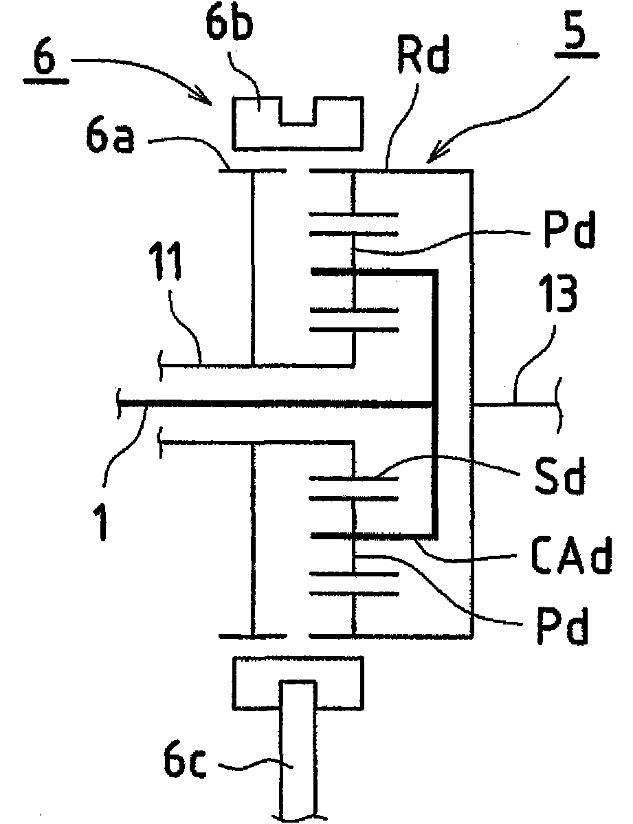
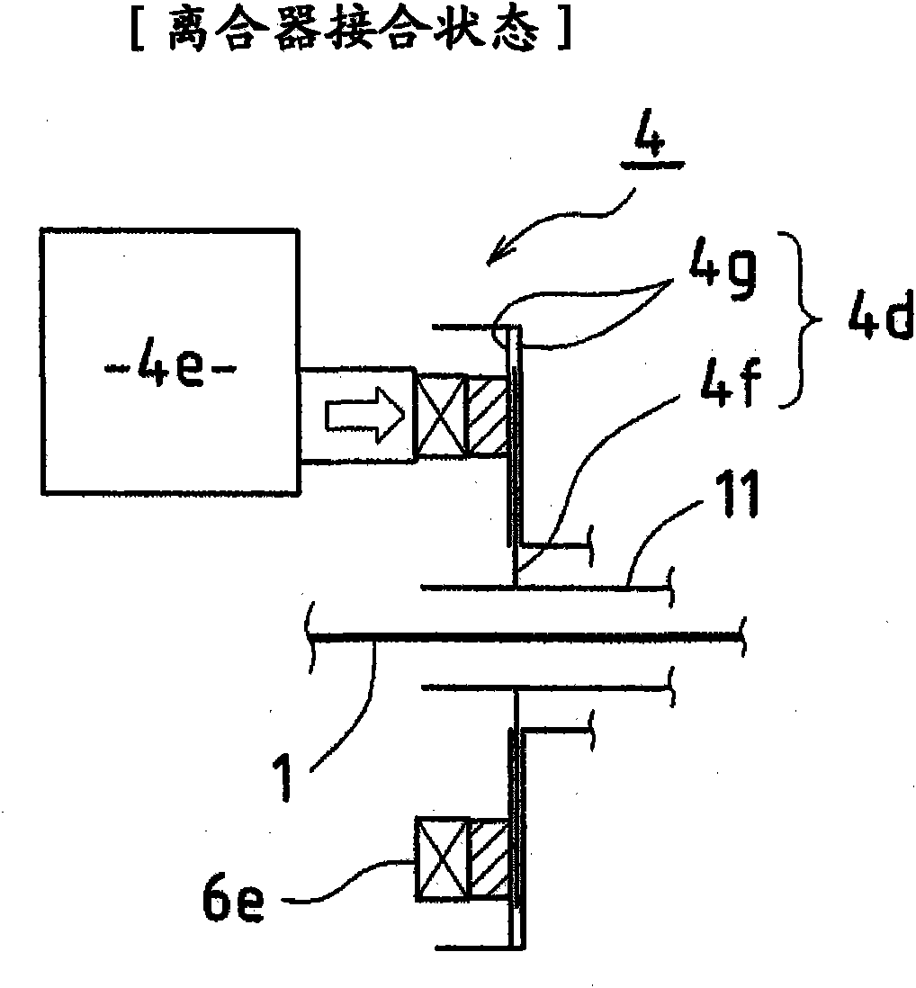
[0125] figure 1 The transfer box shown in includes input shaft 1, rear wheel side output shaft 2 (corresponding to the first output shaft), front wheel side output shaft 3 (corresponding to the second output shaft), power distribution mechanism 4, intermediate differential device 5 (corresponding to the rotation difference absorbing device), differential switching mechanism 6, auxiliary transmission mechanism 7 and control device 8.

[0126] These constituent elements ...


PUM


Abstract

A transfer has a power distribution mechanism 4 securing a two-wheel drive power transmission path that allows rotational power that is input to an input shaft 1 to be output from only a first output shaft 2, or a four-wheel drive power transmission path that allows the rotational power that is input to the input shaft 1 to be output from both the first 2 and a second output shaft 3. The auxiliary gearshift mechanism 7 includes a first auxiliary transmission 20 that is disposed in the first output shaft 2, a second auxiliary transmission 30 that is disposed in the second output shaft 3, and setting apparatuses (40, 50, 60) that cause the first 20 and the second auxiliary transmission 30 to perform gearshift operations as necessary, speed range.

Description

technical field [0001] The invention relates to a vehicle transfer case. Background technique [0002] Traditionally, various systems have been conceived in vehicles, such as part-time four-wheel drive systems, full-time four-wheel drive systems, and backup four-wheel drive systems. [0003] A part-time four-wheel drive system enables a change to a two-wheel drive mode or a four-wheel drive mode. This system is able to transmit sufficient driving force to the four wheels, so it is suitable, for example, for driving on low μ roads such as bad roads, but on the other hand, when driving over higher μ roads such as asphalt roads, for example During a bend, the rotational speed difference between the front and rear wheels increases and as a result braking phenomena occur in the vehicle. In addition, so-called cyclic torque accumulates in the drive mechanism, so that the drive mechanism enters a high-load state, which is undesirable in terms of vehicle drivability and strength o...

Claims


Application Information

Patent Timeline
Patent Type & Authority Applications(China)
IPC IPC(8): B60K17/346
CPCB60K23/0808B60K17/3467
Inventor 吉村孝广
Owner TOYOTA JIDOSHA KK
Why Eureka
Try Eureka