Electric high-speed impact type anti-theft label

An anti-theft label and impact-type technology, which is applied to non-mechanical transmission-operated locks, devices for locking portable objects, and the application of locks, can solve the problems of anti-theft labels losing their anti-theft functions and anti-theft labels without anti-theft functions. Avoidance of possibility, effect of ease of use

Inactive Publication Date: 2010-11-10
ORLEN SENTINEL INDAL SHANGHAI
View PDF5 Cites 4 Cited by
  • Summary
  • Abstract
  • Description
  • Claims
  • Application Information

AI Technical Summary

Problems solved by technology

[0005] The disadvantage of this type of magnetic anti-theft label is that the existing anti-theft labels do not have an absolutely safe anti-theft function, and can be opened by any magnet, making the anti-theft label lose the anti-theft function

Method used


Image

  • Electric high-speed impact type anti-theft label
  • Electric high-speed impact type anti-theft label
  • Electric high-speed impact type anti-theft label

Examples


Embodiment 2

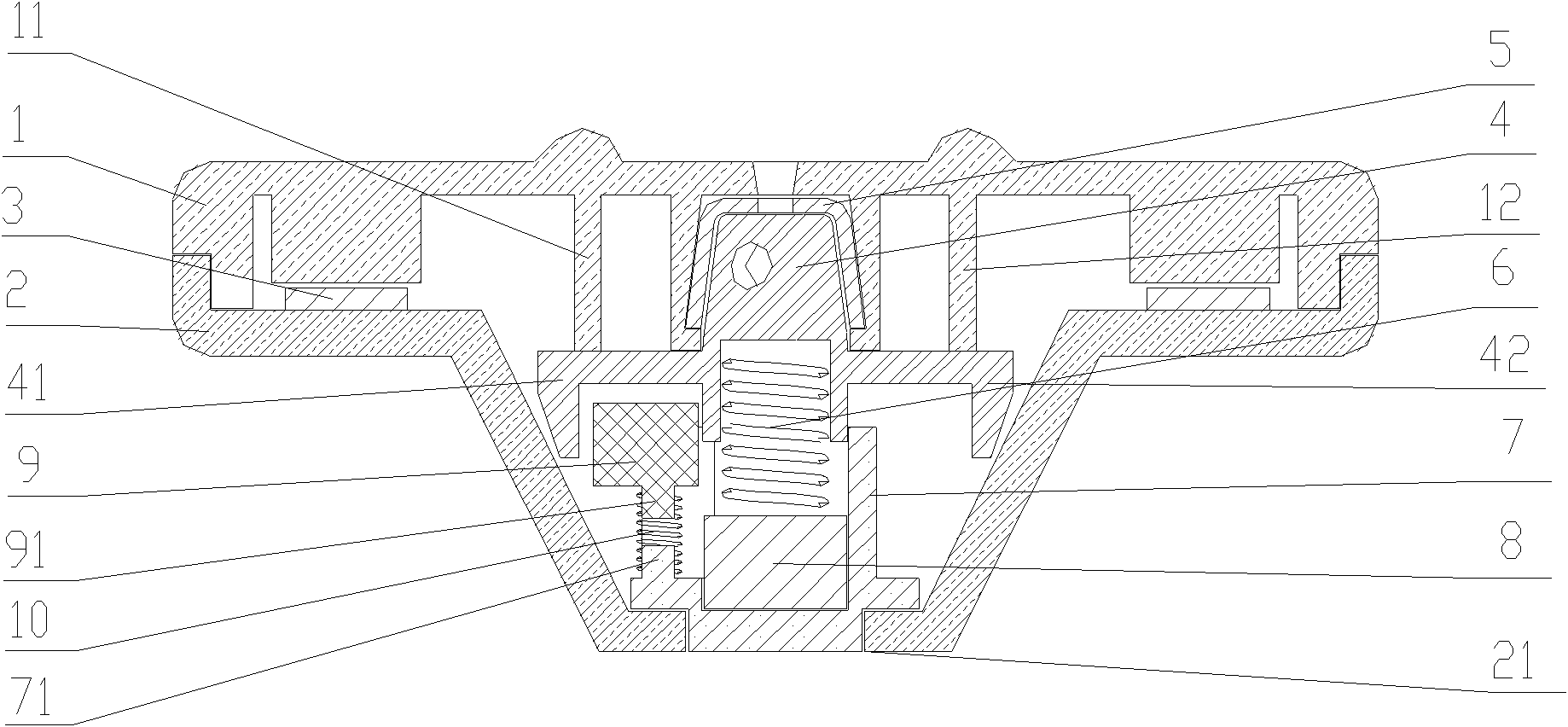
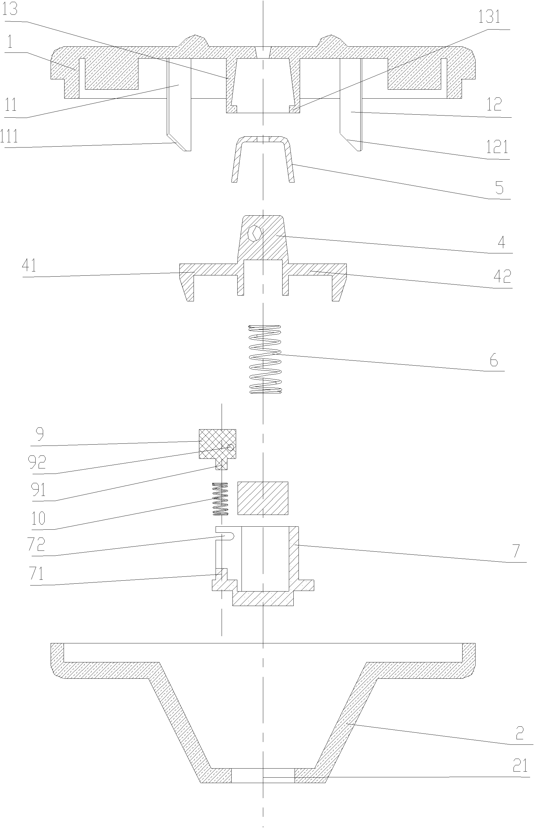
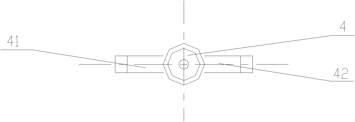
[0107] see Figure 7 It is a schematic cross-sectional structure diagram of Embodiment 2 of the present invention, Figure 8 It is a schematic diagram of the decomposed cross-sectional structure of Embodiment 2 of the present invention, Figure 9 It is a schematic top view structural diagram of the collision block in Embodiment 2 of the present invention, Figure 10 It is a schematic diagram of the three-dimensional structure of the state where the collision block and the locking bead are fixed and disengaged in Embodiment 2 of the present invention and Figure 11It is a schematic diagram of the three-dimensional structure of the impact block hitting the locking bead fixing seat according to Embodiment 2 of the present invention.

[0108] An electric high-speed impact-type anti-theft tag, including a shell composed of an upper cover 1 and a base 2', and a coil alarm 3, an anti-theft nail (not shown in the figure), and a locking mechanism are arranged between the upper cover ...

Embodiment 3

[0119] Such as Figure 12 It is a schematic cross-sectional structure diagram of Embodiment 3 of the present invention, Figure 13 It is a schematic diagram of the decomposed cross-sectional structure of Embodiment 3 of the present invention, Figure 14 It is a schematic top view structural diagram of the rotating body in Embodiment 3 of the present invention, Figure 15 It is a top view structural schematic diagram of the impact block in Embodiment 3 of the present invention, Figure 16 It is a schematic diagram of the three-dimensional structure of the collision block sliding to the bottom of the concave arc of the base in Example 3 of the present invention and Figure 17 It is a schematic diagram of the three-dimensional structure when the impact block hits the locking bead holder in Example 3 of the present invention:

[0120] An electric high-speed impact-type anti-theft tag, including a shell composed of an upper cover 1 and a base 2", and a coil alarm 3, an anti-thef...


PUM


Abstract

The invention relates to an electric high-speed impact type anti-theft label which comprises a housing, an anti-theft bolt and a locking mechanism, wherein the housing consists of an upper cover and a base, the locking mechanism comprises a locking ball, a locking ball fixing seat, a locking ball cap and an elastic piece, the housing is internally provided with a rotating impacting mechanism and a sliding surface downwards pushing the locking ball fixing seat when the locking mechanism rotates, the rotating impacting mechanism comprises a rotating body, a magnetic block and an impact block, the magnetic block is arranged at the bottom of the rotating body, and the impact block is arranged on the rotating body and is positioned at the position of impacting the locking mechanism in the state of high-speed rotation. The invention has the advantage that the impact block in the rotating impacting mechanism produces a movable track different from a static or slow rotation state, thereby impacting the locking mechanism in the anti-theft label for unlocking. The anti-theft label is unlocked by needing a special tool, which effectively avoids the possibility of dismounting the anti-theft label artificially; meanwhile, the anti-theft label can automatically restore the locking state while leaving an unlocker, and has convenient use.

Description

technical field [0001] The invention relates to an anti-theft label, in particular to an electric high-speed impact type anti-theft label, which is widely used for anti-theft of goods in stores or supermarkets. Background technique [0002] Anti-theft labels are widely used in various supermarkets and shopping malls, and are an effective means of reducing theft of goods. [0003] One of the most common anti-theft tags is a locking anti-theft tag. This type of tag consists of a locking bead, a locking bead seat on which the locking bead is installed, and a locking bead cap that cooperates with the locking bead seat in a trapezoidal cross-section to form a lock. The anti-theft nail penetrates into the locking device, and is pressed inward by multiple locking beads so that it cannot be pulled out; when the locking bead cap is separated from the locking bead seat, due to the trapezoidal inner cavity structure, the locking The beads exit radially outward, thereby releasing the a...

Claims


Application Information

Patent Timeline
Patent Type & Authority Applications(China)
IPC IPC(8): E05B73/00E05B47/00
Inventor 赵沛字
Owner ORLEN SENTINEL INDAL SHANGHAI
Why Eureka
Try Eureka