Carriage

A trolley and stage technology, which is applied in the field of trolleys for transporting objects, can solve problems such as unsmooth progress and slowness of operations

Inactive Publication Date: 2010-11-17
SANEI NIYAKUKIKAI KABUSHIKI KAISHA
View PDF5 Cites 2 Cited by
  • Summary
  • Abstract
  • Description
  • Claims
  • Application Information

AI Technical Summary

Problems solved by technology

[0004] Therefore, when folding the trolley, it is different from the folding method that most people are used to when the bottom plate as the loading platform is folded to the rear side of the trolley, that is, to the side...

Method used


Image

  • Carriage
  • Carriage
  • Carriage

Examples


Embodiment 1

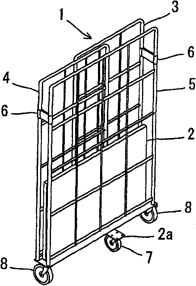
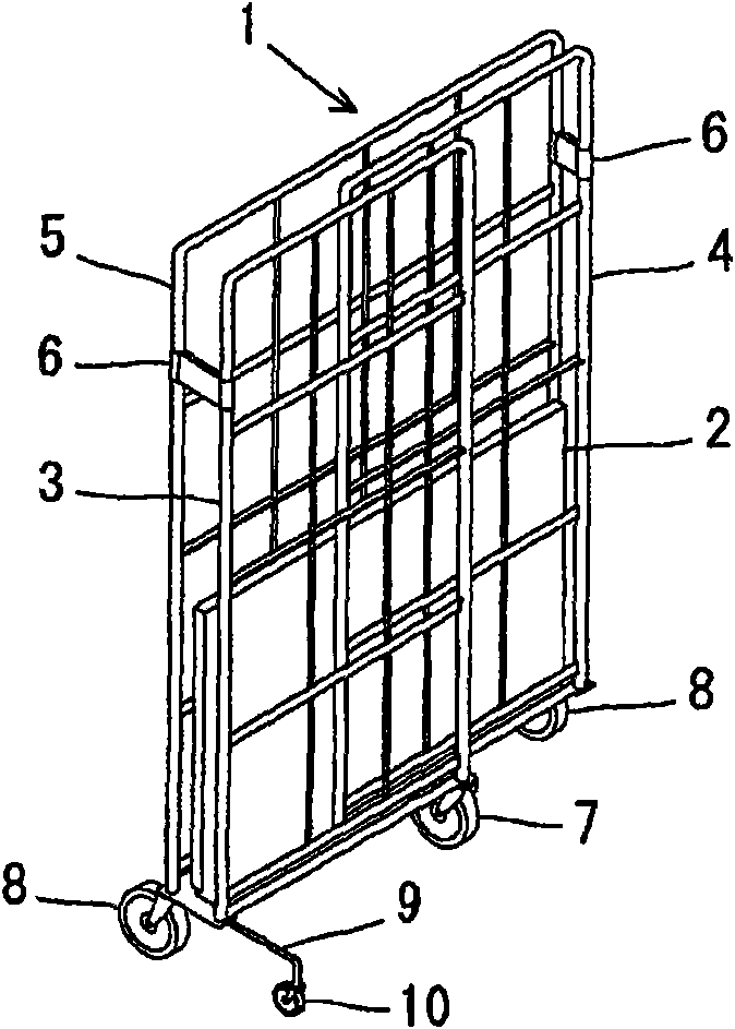
[0048] figure 1 and figure 2 It shows the trolley of this invention, and is a perspective view which shows the folded state of this trolley. figure 1 Represents the state seen from the side of the back frame 5 that becomes the rear side of the trolley, and figure 2 It shows the state viewed from the side of the folded left and right side frames (side frame 3, side frame 4) serving as the front side of the trolley.

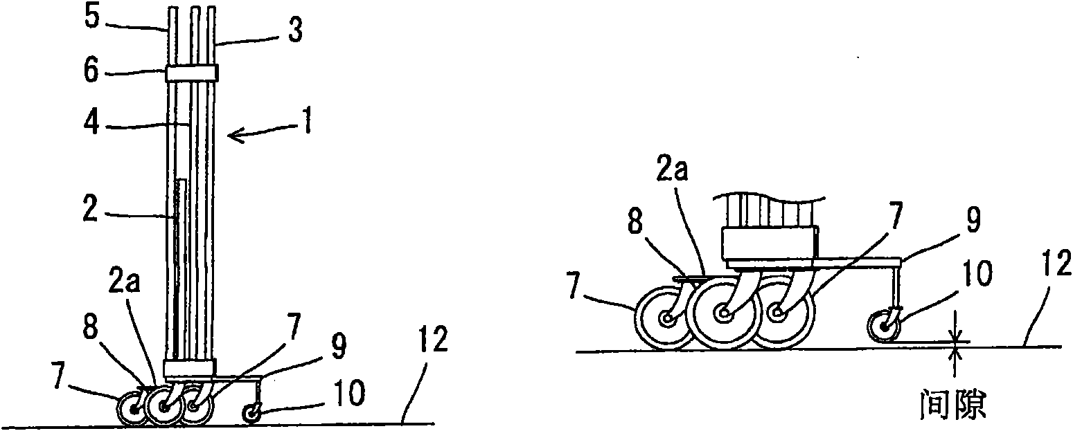
[0049] The trolley 1 is made of the following parts: base plate 2 parts, left and right side frame (side frame 3, side frame 4) parts, back frame 5 parts, front and rear main casters (front side main casters 7, rear side main casters) as wheels for moving. Casters 8), auxiliary casters 10 for making the folded trolley 1 stand on its own safely (cf. figure 2 ).

[0050] according to figure 1 and figure 2 In the folded state of the trolley 1, the bottom plate 2 serving as the loading platform is located in a folded position in a state erected toward the ...

Embodiment 2

[0066] Figure 9 for figure 1 , figure 2 The left and right side frame (side frame 3, side frame 4) parts and back frame 5 parts of the trolley shown are other embodiments composed of plate (side board 3a, side board 4a, back board 5a) parts, and represent the trolley Action diagram of the folding action of .

[0067] in the Figure 9 On the plate parts used to prevent the collapse of the goods provided above the bottom plate 2 of the trolley 1 shown, the side plates 3a and the side plates 4a are respectively freely bendable connected to the side plate 3a and the side plate 4a through the connectors 6a on both sides of the back plate 5a. The back plate 5a side of part 6 is fixed with this back plate 5a, and one side of side plate 3a and side plate 4a is connected via the hinge 6b of connecting piece 6a, therefore, these side plates 3a and side plate 4a can freely rotate via this hinge 6b .

[0068] In addition, the front and rear main casters used as the moving wheels o...


PUM


Abstract

Provided is a carriage. According to the carriage capable of standing on one's self at a forward lean pose during storing, the backwards overturning stability of the carriage during storing can be increased, and the folding can be performed by taking the folding direction of the baseboard as an objective table of the carriage as the back direction identical to the folding direction of the baseboard of the prior carriage. In the carriage, the objective table can be folded to the backward main caster, the front side main caster can move to the back side main caster direction, if the objective table folds to the back side main caster direction and the front side main caster moves to the back side main caster direction, the auxiliary caster is more projected to the front side than the front side main caster. Its configuration is that, when the objective table folds to the direction of the back side main caster (8) and the front side main caster (7) moves to the direction of the back side main caster (8), at least one main caster in the front side main casters (7) are more projecting to the back side than the rear side main caster (8).

Description

technical field [0001] The present invention relates to a trolley for conveying articles, and more specifically, to a trolley capable of being stored in a self-supporting state. Background technique [0002] All the time, the trolley that is used for conveying article is in order to take up as little space as possible when being received or vehicle conveyance, and also can fold when maintaining self-supporting state, for example the trolley invented by the applicant (see patent document 1). [0003] This trolley supports the folded and self-standing trolley in a forward leaning posture through the auxiliary casters, so that the bottom plate as the loading platform specially made for carrying goods can be located at the front position of the folded trolley, making it self-standing. The center of gravity of the trolley is as far forward as possible. [0004] Therefore, when folding the trolley, it is different from the folding method that most people are used to when the bot...

Claims


Application Information

Patent Timeline
IPC IPC(8): B62B3/14B62B3/02
CPCB62B3/002B62B3/025
Inventor 金谷贤一
Owner SANEI NIYAKUKIKAI KABUSHIKI KAISHA
Why Eureka
Try Eureka