Beam erecting method

A technology for erecting beams and beam bodies, applied in the field of highway beam erecting, can solve problems such as long construction period, and achieve the effects of improving construction efficiency, ensuring safety and improving efficiency

Active Publication Date: 2012-11-07
中国建筑土木建设有限公司
View PDF0 Cites 0 Cited by
  • Summary
  • Abstract
  • Description
  • Claims
  • Application Information

AI Technical Summary

Problems solved by technology

[0010] The purpose of the present invention is to provide a beam erecting method to solve the problem of long construction period of existing highway bridge erecting methods

Method used


Image

  • Beam erecting method
  • Beam erecting method
  • Beam erecting method

Examples


Embodiment Construction

[0028] The main idea of ​​the present invention is to adopt the method of tilting and lifting the beam body from the bottom of the bridge pier when installing the beam body, instead of the traditional way of translating the beam body above the bridge pier, so as to improve the installation efficiency of the beam body and shorten the construction period .

[0029] The present invention will be described in detail below in conjunction with the accompanying drawings.

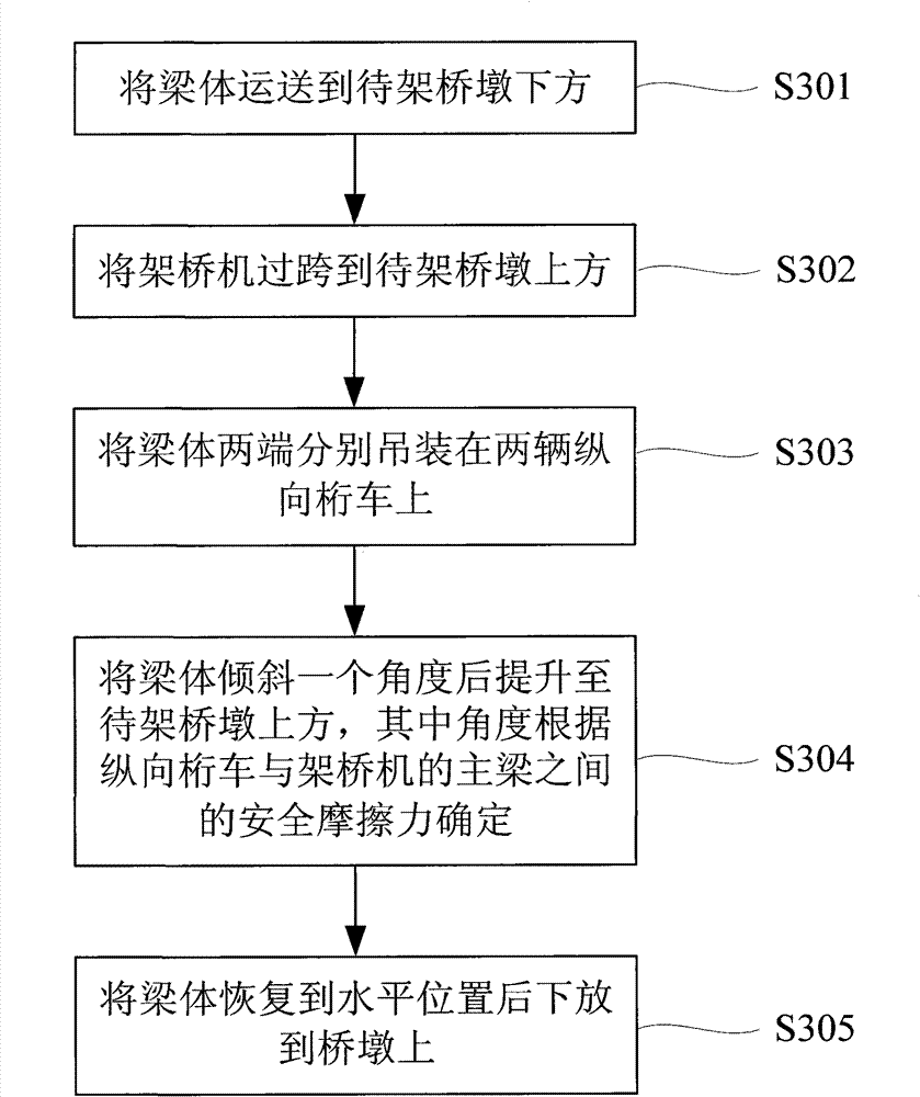
[0030] See image 3 , which is a flow chart of an embodiment of the beam erecting method of the present invention, which includes the following steps:

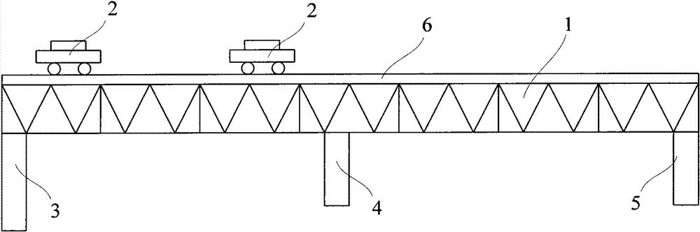
[0031] S301, transporting the girder body under the pier to be erected.

[0032] S302. Overspan the bridge erecting machine over the pier to be erected, and make the two longitudinal girders on the bridge erecting machine correspond to the two ends of the girder body.

[0033] S303, hoisting the two ends of the beam body on two longitudinal truss trucks respecti...


PUM


Abstract

The invention provides a beam erecting method which utilizes a bridge erecting machine to carry out bridge erecting construction. The bridge erecting machine comprises a main beam and two longitudinal joist barrows operating on the main beam. The beam erecting method comprises the following steps of: (1) transporting a beam body below a pier to be erected; (2) making the bridge erecting machine striding over the pier to be erected, and making the two longitudinal joist barrows on the bridge erecting machine correspond to both ends of the beam body; (3) respectively hoisting both ends of the beam body on the two longitudinal joist barrows; (4) inclining the beam body by an angle and then lifting the beam body above the pier to be erected, wherein the angle is determined according to safetyfriction between the longitudinal joist barrow and the main beam of the bridge erecting machine; and (5) restoring the beam body to the horizontal position and then lowering to the pier. The invention has the advantages of high efficiency, short construction period and high safety.

Description

technical field [0001] The invention relates to a beam erecting method, in particular to a road beam erecting method which can greatly shorten the construction period. Background technique [0002] With the rapid development of my country's economy, more and more expressways need to be built. In the erection of expressways, bridge erecting machines are commonly used equipment. See figure 1 , which is a structural diagram of an existing bridge erecting machine, which mainly includes a main girder 1, a longitudinal truss car 2 on the girder, a front leg 3, a middle leg 4 and a rear leg 5. The main girder 1 is a triangular steel frame structure, on which a guide rail 6 is laid, and two longitudinal truss vehicles 2 run on the guide rail 6 . The front outrigger 3 is fixed on the front end of the main beam 1, and the front outrigger 3 is equipped with a telescopic oil cylinder. The middle outrigger 4 and the rear outrigger 5 are arranged on the middle part and the rear end of ...

Claims


Application Information

Patent Timeline
Patent Type & Authority Patents(China)
IPC IPC(8): E01D21/00
Inventor 陈锦明刘永福杨世廷史占云朱长亮
Owner 中国建筑土木建设有限公司
Why Eureka
Try Eureka