Groove bottom-reinforced fully lined debris flow drainage groove and construction method thereof

A drainage channel and debris flow technology, applied in dikes, coastline protection, dams, etc., can solve the problems of full channel damage, difficult to popularize and apply in large areas, drainage channel damage, etc., to save engineering maintenance costs, ensure operation safety, The effect of low construction cost

Inactive Publication Date: 2010-11-17
INST OF MOUNTAIN HAZARDS & ENVIRONMENT CHINESE ACADEMY OF SCI
View PDF6 Cites 21 Cited by
  • Summary
  • Abstract
  • Description
  • Claims
  • Application Information

AI Technical Summary

Problems solved by technology

[0003] Due to its much higher bulk density than water, debris flow has a special fluid structure containing clastic soil, so the movement of debris flow shows the characteristics of high inertia, strong transport force, huge impact force, strong abrasive force, etc. The bottom of the lining-type debris flow drainage channel is highly abrasive and severely damaged by impact, with adverse consequences of local damage or even complete tank failure
[0004] In order to prevent the debris flow from eroding the bottom of the fully-lined debris flow drainage channel, it is usually used to increase the concrete grade and set up the old rail slide bed protection, but the cost of these measures is too high to be widely used. On the other hand, even if it is adopted These measures may also lead to the destruction of the entire guide groove due to local weak point damage.
[0005] The utility model pa

Method used


Image

  • Groove bottom-reinforced fully lined debris flow drainage groove and construction method thereof
  • Groove bottom-reinforced fully lined debris flow drainage groove and construction method thereof
  • Groove bottom-reinforced fully lined debris flow drainage groove and construction method thereof

Examples


Embodiment 1

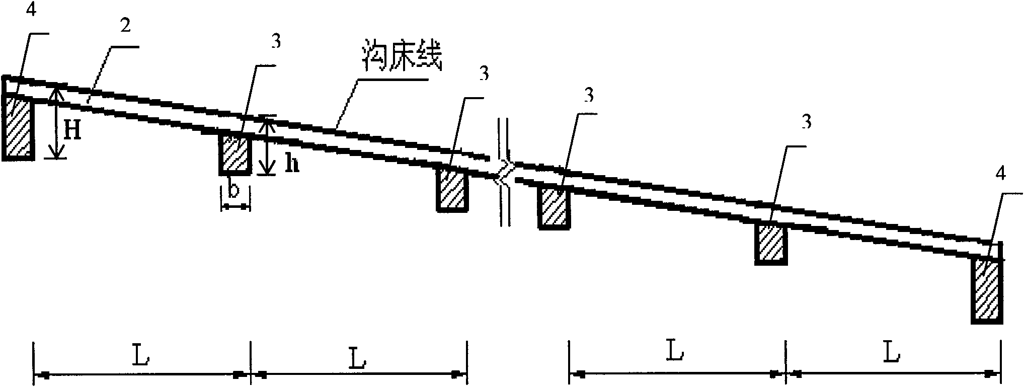
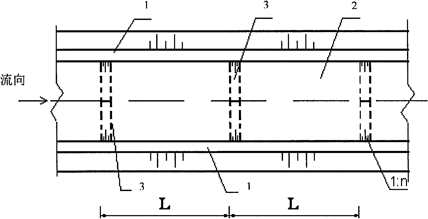
[0038] Such as figure 2 , image 3 , Figure 4 , Figure 5 shown. For a watershed area of ​​1.5km 2 , The accumulation fan slope is 18%. On the debris flow accumulation fan, a V-shaped full-lined debris flow drainage trough reinforced at the bottom of the trough is built. The length of the trough is 200m, including the fully lined trough bottom plate 2 and the side walls 1 of the trough on both sides. In the foundation and below the guide groove, there are 11 submerged sills that run transversely along the guide groove, are connected with the bottom plate 2 of the guide groove, are distributed at certain intervals, and have a certain effective buried depth. The distance L between the submerged sills is 20.0m; the width b of the submerged sills is 1.0m in the longitudinal direction along the side wall 1 of the guide trough; the engineering structure of the submerged sills adopts concrete structure; The design shape is consistent, it is V-shaped, the upper surface of the ...

Embodiment 2

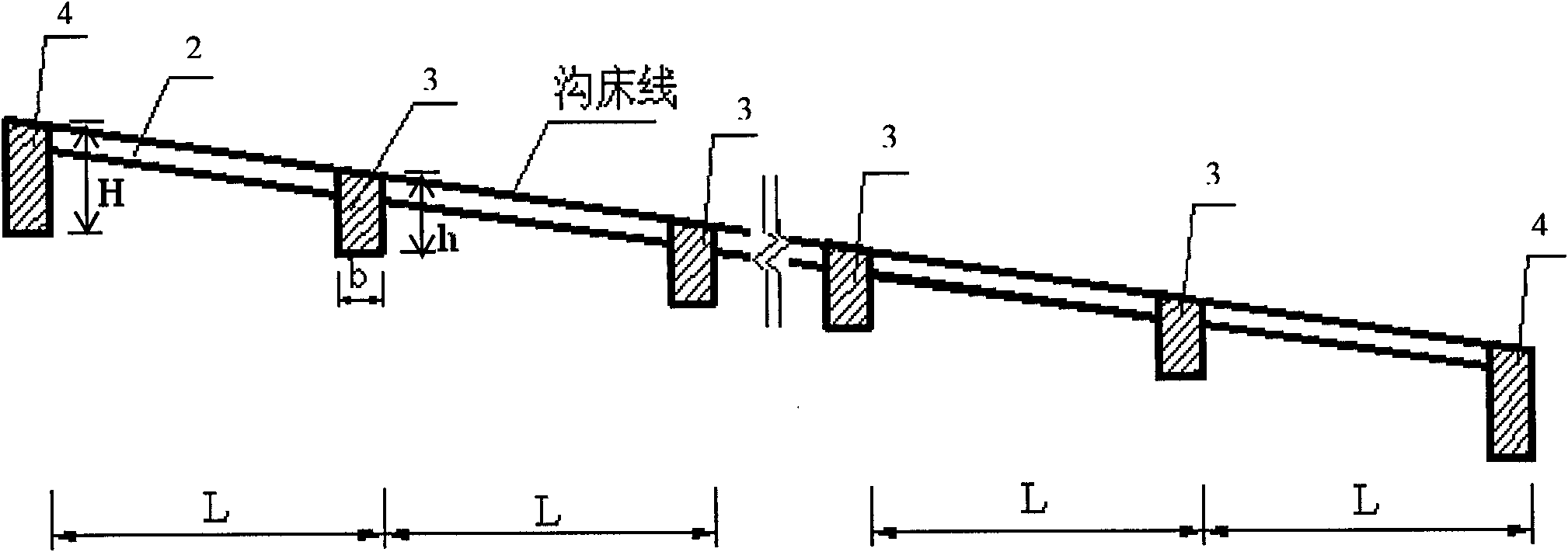
[0044] Such as figure 1 , Figure 6 , Figure 7 , Figure 8 shown. For a watershed area of ​​20.0km 2 , The slope of the accumulation fan is 5%. The same thing as Embodiment 1 will not be repeated, and the difference is that the length of the guide trough is 800m, and there are 9 sills, and the 2 sills at the entrance and exit of the guide trough are deepened sills 4. The remaining 7 diving sills at other positions of the guide groove are common diving sills 3 . The shape of the bottom of the guide trough is trapezoidal; the distance L between the submerged sills is 100.0m; along the longitudinal direction of the side wall 1 of the guide trough, the width b of the submerged sill is 2.5m; the engineering structure of the submerged sill adopts reinforced concrete structure; The shape of the upper surface of the submerged sill is consistent with the design shape of the bottom of the groove, which is trapezoidal. The transverse vertical slope of the bottom plate 2 of the li...


PUM

PropertyMeasurementUnit
Spacingaaaaaaaaaa

Abstract

The invention discloses a groove bottom-reinforced fully lined debris flow drainage groove and a construction method thereof. The groove bottom-reinforced fully lined debris flow drainage groove comprises a fully lined drainage groove bottom plate and drainage groove side walls on the two sides of the bottom plate; a plurality of submerged sills which pass through along the drainage groove transversely, are connected with the drainage groove bottom plate, are distributed at intervals, and have a certain effective burial depth are arranged in the foundation and below the drainage groove; the submerged sills at the inlet and the outlet of the drainage groove are deepened submerged sills, and the submerged sills at other positions of the drainage groove are common submerged sills; and the effective burial depth of each of the deepened submerged sills is larger than that of each of the common submerged sills, and the deepened submerged sills extend to the bottom of the foundation of each of the drainage groove side walls on the two sides so as to form a triangular wedge-shaped body respectively. Compared with the prior art, the groove has the advantages of making full use of the bed-reinforcing effect of the submerged sills, reinforcing the bottom of the drainage groove in sections, avoiding danger to the entire drainage groove due to the damage of local drainage groove bottom, guaranteeing the operation safety of the drainage groove adequately, increasing small working amount and saving a large amount of engineering maintenance cost, along with low construction cost.

Description

technical field [0001] The invention relates to a mud-rock flow prevention and control technology, in particular to a fully-lined mud-rock flow drainage channel with reinforced bottom and a construction method thereof. Background technique [0002] Debris flow disaster is one of the main types of geological disasters in my country. With the development of the mountainous area economy and the deepening of the western development, the demand for debris flow engineering control is becoming more and more vigorous. The fully-lined debris flow drainage channel is the most common engineering measure for debris flow engineering control. It has been widely used in the past and will also be necessary in future debris flow engineering control. Will be heavily applied. [0003] Due to its much higher bulk density than water, debris flow has a special fluid structure containing clastic soil, so the movement of debris flow shows the characteristics of high inertia, strong transport force...

Claims


Application Information

Patent Timeline
IPC IPC(8): E02B3/10
Inventor 陈晓清游勇李德基崔鹏高全
Owner INST OF MOUNTAIN HAZARDS & ENVIRONMENT CHINESE ACADEMY OF SCI
Why Eureka
Try Eureka