Pressing mechanism of oil consumption measuring device of vehicle oil tank

A technology of measuring device and pressing mechanism, applied in the direction of buoy liquid level indicator, etc., can solve the problems of easy failure, high manufacturing cost, unfavorable test accuracy, etc., reduce parts and processing and assembly, avoid collision and collision, and simple operation reliable effect

Inactive Publication Date: 2011-10-05
上海市长途汽车运输有限公司
View PDF1 Cites 0 Cited by
  • Summary
  • Abstract
  • Description
  • Claims
  • Application Information

AI Technical Summary

Problems solved by technology

The rope pulled up needs to be converted into a horizontal pressing action, and the middle is slipped, and the steering transmission structure is complex, difficult to manufacture and debug, high in manufacturing cost, and prone to failure
Larger steering vibration affects the measurement accuracy, and the action of pulling up the rope is consistent with the height of the oil level in the fuel tank is also a factor that is unfavorable to the measurement accuracy, so it is necessary to further improve

Method used


Image

  • Pressing mechanism of oil consumption measuring device of vehicle oil tank
  • Pressing mechanism of oil consumption measuring device of vehicle oil tank
  • Pressing mechanism of oil consumption measuring device of vehicle oil tank

Examples


Embodiment 1

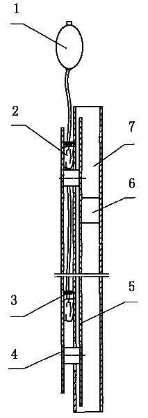
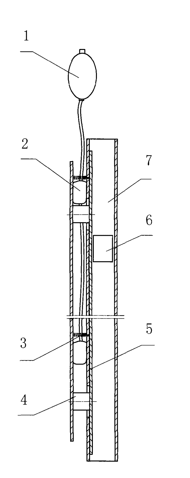
[0030] as attached figure 1 , 2 As shown, a compression mechanism of a vehicle fuel tank fuel consumption measurement device includes an upper hand-held handle and a lower vertical test tube 7. A float 6 is placed in the lumen of the test tube 7, and a compression plate 5 is arranged on the side of the float 6. , the pressing plate 5 can move in the direction perpendicular to the axis of the lumen, in two positions of pressing the float 6 and releasing the float 6, the force of the pressing plate 5 pressing and releasing the float is composed of the spring 3 and the inflation Airbag 2 provided. The side portion of the pressing plate 5 is fixedly connected with a parallel linkage plate 4 , and an inflatable air bag 2 and a tension spring 3 are arranged inside the linkage plate 4 .

[0031] When the air bag 2 is deflated, the pressure plate 5 is pressed in the direction of the tension by the tension of the tension spring, and the float 6 is pressed, positioned in the test tube...

Embodiment 2

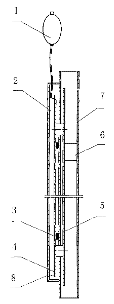
[0034] as attached image 3 , 4 As shown, a compression mechanism of a vehicle fuel tank fuel consumption measurement device includes an upper hand-held handle and a lower vertical test tube 7. A float 6 is placed in the lumen of the test tube 7, and a compression plate 5 is arranged on the side of the float 6. , the pressing plate 5 can move in the direction perpendicular to the axis of the lumen, in two positions of pressing the float 6 and releasing the float 6, the force of the pressing plate 5 pressing and releasing the float is composed of the spring 3 and the inflation Airbag 2 provided. The side portion of the pressing plate 5 is fixedly connected with a parallel linkage plate 4 , an inflatable air bag 2 is arranged outside the linkage plate 4 , and an elastic force spring 3 is arranged inside the linkage plate 4 .

[0035] When holding the inflatable ball 1 at the handle, repeatedly pressing the inflatable ball 1 to inflate the inflatable air bag 2, the volume of th...


PUM


Abstract

The invention relates to a pressing mechanism of a testing floater in an oil consumption measuring device for vehicles. A pressing mechanism of an oil consumption measuring device of a vehicle oil tank comprises a hand-hold handle arranged on the upper part and a vertical testing pipe (7) arranged on the lower part, wherein a floater (6) is arranged in a pipe cavity of the testing pipe (7); a pressing plate (5) is arranged on the side part of the floater (6) and can move in the direction which is perpendicular to the axis of the pipe cavity between a floater (6) pressing position and a floater (6) loosening position; and the forces for pressing and loosening the floater by the pressing plate (5) are provided by a spring (3) and an inflation air bag (2). By adopting the pressing mechanism, structures of a pressing mechanism and a loosening mechanism of the floater are simplified, parts, machining assembly and the adjustment quantity are reduced, and the pressing mechanism is simple, convenient and reliable to move and is convenient, sanitary and safe to use.

Description

(1) Technical field [0001] The invention relates to a fuel consumption measuring device, in particular to a pressing mechanism for a test float in a vehicle fuel consumption measuring device. (2) Background technology [0002] The fuel consumption measuring device of the vehicle fuel tank in the prior art is that the fuel gauge is directly inserted into the fuel tank hole, and the indicator of the vehicle fuel gauge is directly connected to the float. Fuel gauge shows fuel consumption. Due to the limitation of the angle of the oil hole, the oil gauge is easy to be placed obliquely, and the bubbles on the oil surface affect the movement of the float and other structural factors, which affect the accuracy of the measurement. In addition, most of the fuel gauges in the cab have no data indication or have a large indication range, poor accuracy and limited adaptation conditions. Therefore, the fuel volume in the fuel tank cannot be accurately determined. [0003] For long-dist...

Claims


Application Information

Patent Timeline
Patent Type & Authority Patents(China)
IPC IPC(8): G01F23/30G01F23/64
Inventor 谈广俊张敬伟杜敏项阳陈闵叶
Owner 上海市长途汽车运输有限公司
Why Eureka
Try Eureka