
An arrangement for optical representation and wireless communication

A technology of equipment and radio waves, which is applied in the direction of feed, antenna, resonant antenna, etc. in the middle position between antenna endpoints, can solve the problems of affecting and limiting the capacity/quality of antenna equipment, and achieve improved transmission capacity and good reception/transmission capabilities , the effect of good light performance

Inactive Publication Date: 2010-11-17
TELEFON AB LM ERICSSON (PUBL)
View PDF4 Cites 8 Cited by
  • Summary
  • Abstract
  • Description
  • Claims
  • Application Information

AI Technical Summary

Problems solved by technology

It has to be on the back of the display or in a frame surrounding the display which greatly limits the capacity / quality of the antenna device
The basic problem is that the antenna device and the display device in known devices interface with each other or negatively affect each other, and it has not been possible to provide two of these functionalities (the functionality of light representation and the function of receiving / transmitting radio waves etc. performance) combined equipment that meets high requirements at the same time

Method used


Image

  • An arrangement for optical representation and wireless communication
  • An arrangement for optical representation and wireless communication
  • An arrangement for optical representation and wireless communication

Examples


Embodiment Construction

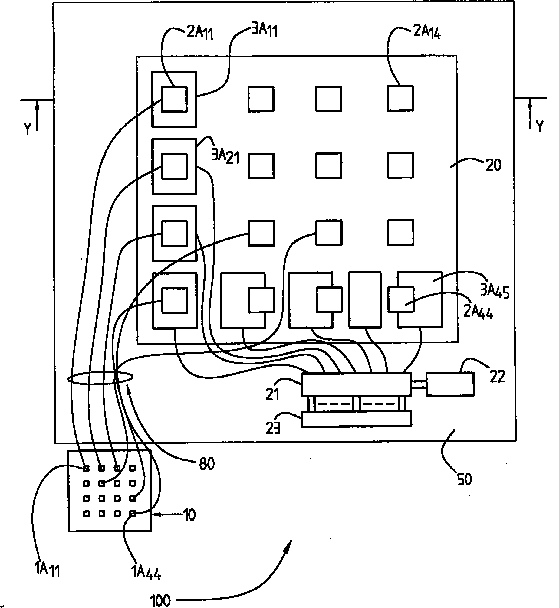
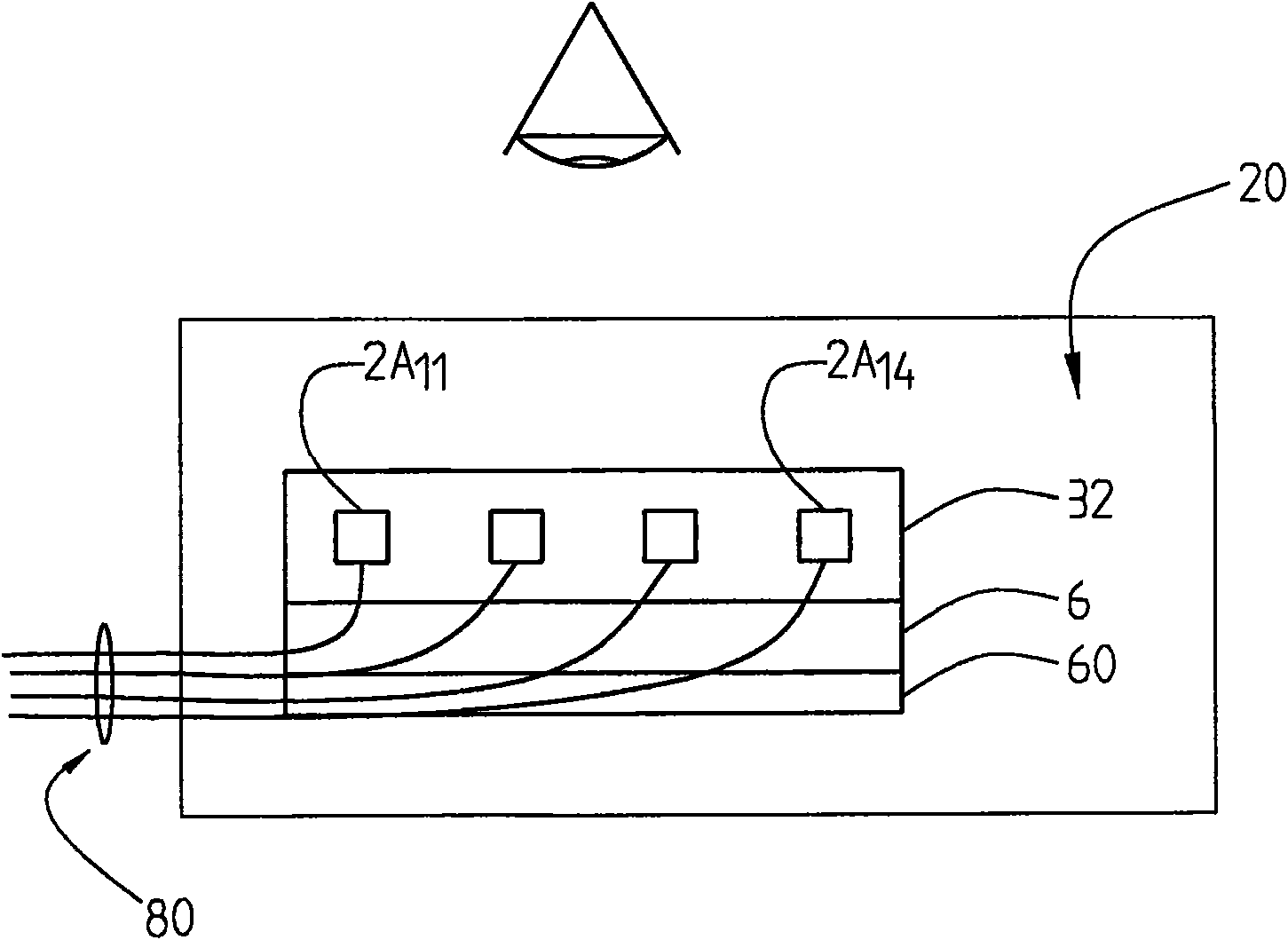
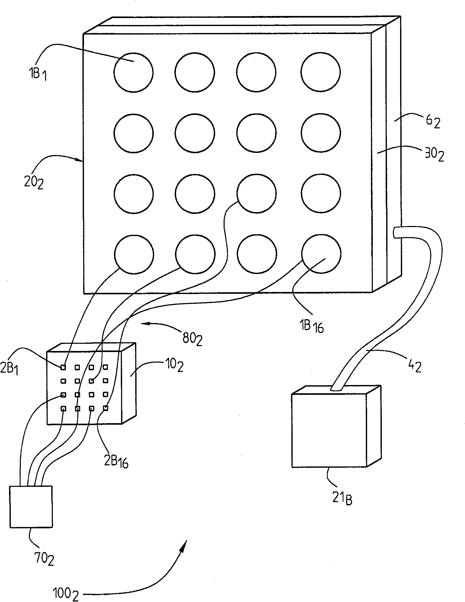
[0021] figure 1 A display and antenna device 100 is shown comprising a primary functional display component 10 comprising a plurality of small pixel elements 1A 1 ,...,1A 44 , these small pixel elements are connected to image generating components, such as a graphics card (not shown). The primary function display unit 10 acts as an image source with high resolution and high intensity. These small pixel elements, in particular light emitting diodes (LEDs), are connected to a larger passive second pixel element 2A of the main display 20 by means of a bundle of optical fibers 80 acting as waveguides. 11 ,...,2A 44 for the visual representation of images. Accordingly, the miniature image generated in the primary function display part 10 is enlarged and projected on the main display screen 20 via the optical fiber 80 . Miniature images can be produced by conventional digital projector technology. However, it is an advantage that the generation of the image can be done with a ...


PUM


Abstract

The present invention relates to a display arrangement (100) comprising a functional primary display means (10) and a main display means (20). The functional, primary display means (10) comprises a number of first, small pixel elements (1A11,..., 1A44) and comprises or communicates with image generating means for generation of a high resolution miniature image. The main display means (20) comprises a dielectric material which is transparent to radio-, and / or millimetre waves and / or microwaves and comprises a number of second, passive, pixel elements (2A11,..., 2A44) substantially corresponding to the number of first, pixel elements. Said second pixel elements are considerably larger than said first pixel elements and each first pixel element is connected to a second pixel element by means of an optical transmission means (80) for transfer of optical image information. The main display means is adapted to visually represent the transferred optical information as an enlarged image and receiving / transmitting means for communication of radio-, millimeter wave or microwave signals are arranged in or on the main display means such that reception / transmission can take place substantially independently of the optical representation.

Description

technical field [0001] The invention relates to a display device comprising display means associated with receiving and / or transmitting means for communication of radio wave, millimeter wave or microwave signals. In particular, the invention relates to a display device having receiving and / or transmitting capabilities for a wireless communication terminal. Background technique [0002] A wireless communication terminal must be equipped with a display screen and receiving and transmitting parts, more precisely antenna parts. Importantly, the display component is capable of presenting light information with high resolution and high quality. It is also important that the receiving and transmitting capabilities of the wireless communication terminal are good. Among other things, it should be possible to provide good coverage of all possible radio communication channels (assuming that the wireless communication terminals communicate by means of radio waves). For a communicatio...

Claims


Application Information

Patent Timeline
IPC IPC(8): G02B6/06H01Q1/12H01Q1/24H01Q1/38H01Q9/04H01Q9/16H01Q1/22
CPCH01Q9/0407H01Q9/16H01Q1/243H01Q1/2258H01Q1/1271H01Q1/38
Inventor F·哈里森J·梅德博
Owner TELEFON AB LM ERICSSON (PUBL)
Learn More