
Device for installing and adjusting potentiometer

A technology for installation and adjustment of potentiometers, applied in the field of potentiometers, can solve problems such as inability to adapt to different potentiometer adjustments and installations, unstable linearity of potentiometer adjustment, and deviation of the axis of the adjustment shaft from the normal position to achieve a fixed effect. Good, ensure accuracy, avoid the effect of linearity instability

Inactive Publication Date: 2012-02-08
SOUTH CHINA UNIV OF TECH
View PDF0 Cites 0 Cited by
  • Summary
  • Abstract
  • Description
  • Claims
  • Application Information

AI Technical Summary

Problems solved by technology

However, most of the commonly used potentiometer adjustment shafts are relatively short at present, and cannot adapt to the adjustment and installation of different potentiometers. Simply increasing the length of the adjustment shaft can meet the requirements of the adjustment length, but it cannot meet the requirements of the adjustment shaft in the radial direction. The stability of the adjustment shaft is easy to make the axis of the adjustment shaft deviate from the normal position, resulting in unstable linearity of the potentiometer adjustment, and in severe cases, it will also cause damage to the potentiometer.
At the same time, the number of rotations of the potentiometer also needs to be limited to a certain extent. If its rotation is not effectively stopped in time, the potentiometer may be damaged due to excessive force, and the current potentiometer adjustment device also has a limited number of rotations. less than limited defects

Method used


Image

  • Device for installing and adjusting potentiometer
  • Device for installing and adjusting potentiometer

Examples


Embodiment Construction

[0018] The present invention will be further described in detail below in conjunction with the embodiments and the accompanying drawings, but the embodiments of the present invention are not limited thereto.

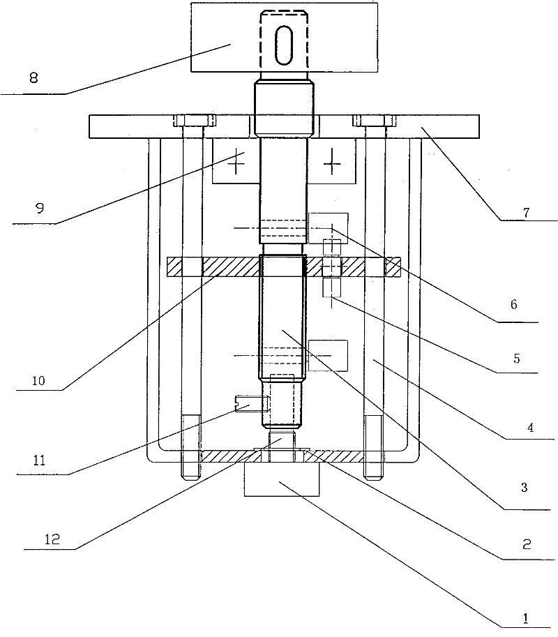
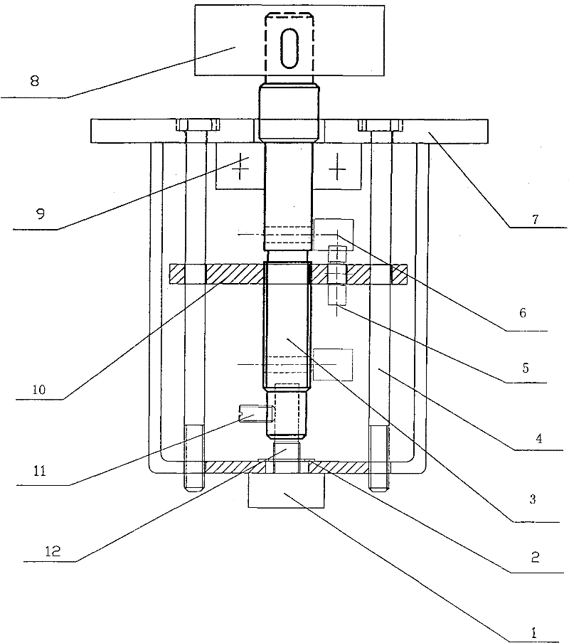
[0019] In this embodiment, a potentiometer is installed and adjusted, and its structure is as follows: figure 1 As shown, it includes a fixed bracket 7 and an adjustment mechanism. The adjustment mechanism includes an adjustment shaft 3 and a limit assembly. The adjustment shaft 3 is located at the center of the fixed bracket 7 and passes through the fixed bracket 7. Connection, the upper end of the adjustment shaft 3 is provided with a rotary handle 8, the lower end of the adjustment shaft 3 is provided with a blind hole that is connected with the potentiometer 1, and a plurality of positioning screws 11 for fixing the potentiometer are provided on the outside of the blind hole, and the limit assembly is located on the adjustment shaft 3 Middle.

[0020] The fixed brac...


PUM


Abstract

The invention provides a device for installing and adjusting a potentiometer. The device for installing and adjusting the potentiometer comprises a fixed bracket and an adjusting mechanism, wherein the adjusting mechanism comprises an adjusting shaft and a limit component; the adjusting shaft is arranged in the center of the fixed bracket and passes through the fixed bracket; the adjusting shaft is connected with the fixed bracket through a bearing; a rotary handle is arranged at the upper end of the adjusting shaft; a blind hole which is connected with the potentiometer in a matching way is formed at the lower end of the adjusting shaft; a plurality of positioning screws for fixing the potentiometer are arranged on the outside of the blind hole; and the limit component is arranged in themiddle of the adjusting shaft. The device for installing and adjusting the potentiometer has the advantages that: the potentiometer is locked and fixed by nuts and the plurality of positioning screwsrespectively, so the structure is simple and the fixing effect is good; an axle center of the adjusting shaft is stabilized by a flat steel plate, so the accuracy of adjusting the potentiometer is guaranteed and the phenomenon of unstable linearity of potentiometer adjustment caused by the overlong adjusting shaft is avoided; and the limit component is arranged in the middle of the adjusting shaft, so the rotation of the potentiometer can be stopped in time and the rotation turns in the process of adjusting the potentiometer are effectively controlled.

Description

technical field [0001] The invention relates to the field of potentiometers, in particular to a potentiometer installation adjustment device. Background technique [0002] At present, the use of potentiometers is ubiquitous in the world. The potentiometer is actually a variable resistor. Because its resistance is constantly changing, the current and voltage in the circuit can be constantly changing. Therefore, it is widely used in various large-scale electronic simulations. system. Especially in entertainment venues, there will be many electronic simulation systems for tourists to demonstrate and experience. The general demonstration system changes the magnitude of the current in the system circuit by turning the potentiometer to adjust the shaft, so that the analog output continuously changes, so as to obtain different playback images. However, most of the commonly used potentiometer adjustment shafts are relatively short at present, and cannot adapt to the adjustment and...

Claims


Application Information

Patent Timeline
Patent Type & Authority Patents(China)
IPC IPC(8): H01C10/14
Inventor 谢小鹏贾尚雨
Owner SOUTH CHINA UNIV OF TECH
Learn More