Fan strip label shaping and shearing device

A cutting device and label technology, applied in the direction of manufacturing tools, other manufacturing equipment/tools, etc., can solve the problem of inability to form fan strip labels, and achieve the effect of simple structure, continuous forming, and convenient use.

Inactive Publication Date: 2010-12-01
SHANDONG UNIV +1
View PDF5 Cites 7 Cited by
  • Summary
  • Abstract
  • Description
  • Claims
  • Application Information

AI Technical Summary

Problems solved by technology

[0003] Patent CN2628195Y provides a special device for cutting metal strips. This device can only cut the end of the label into a semicircular head, and can only cut straight labels, but cannot form scalloped labels.
[0004] Searched v...

Method used


Image

  • Fan strip label shaping and shearing device
  • Fan strip label shaping and shearing device
  • Fan strip label shaping and shearing device

Examples


Embodiment Construction

[0019] The present invention will be further described below in conjunction with the accompanying drawings and embodiments.

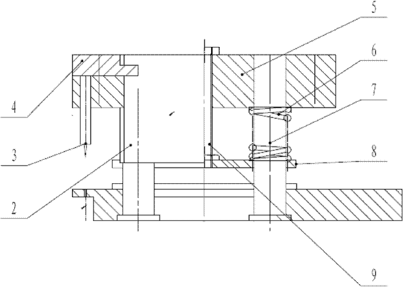
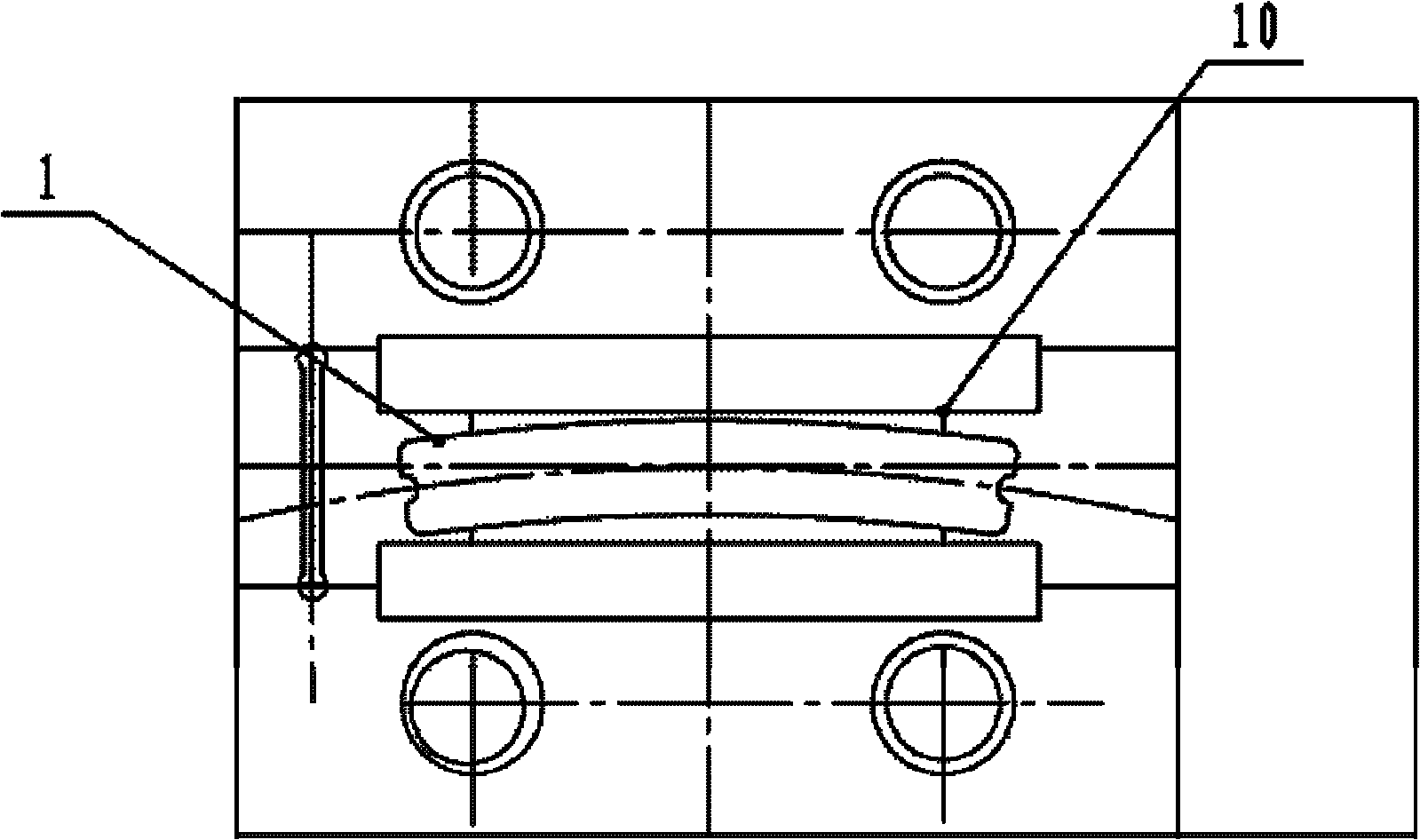
[0020] figure 2 , image 3 Among them, the label forming is completed by the concave mold 1 and the convex mold 2 with the same profile, and the installation reference hole of the convex mold 2 is consistent with the concave mold 1 to ensure the centering of the convex and concave molds. The movement of the punch 2 is positioned by 4 guide columns to ensure the correct moving position; the centering of the strip above the die 1 is guaranteed by two guide plates 10; Complete, and the waste material shearing has special shearing knife 3 to complete.

[0021] The die 1 and the punch 2 are both closed profiles consistent with the label to be cut, with parallel arcs on both sides and radial lines with a certain angle at both ends. The arcs and radial lines have arc transitions. There is a concave semicircle in the middle of the radial lines at both ends....


PUM


Abstract

The invention relates to a fan strip label shaping and shearing device, which has the advantages of simple structure, convenient use, one-step shaping and the like. The device comprises a female die and a male die, wherein contours of the two dies are consistent with the peripheral shape of a shaped label; a fit clearance is reserved between the two dies; the male die is connected with a datum plate; the shearing device is arranged on the datum plate; the datum plate is arranged on a guiding device; the male die is matched with a discharging plate; the discharging plate is connected with the datum plate; and a resetting device is arranged between the discharging plate and the datum plate.

Description

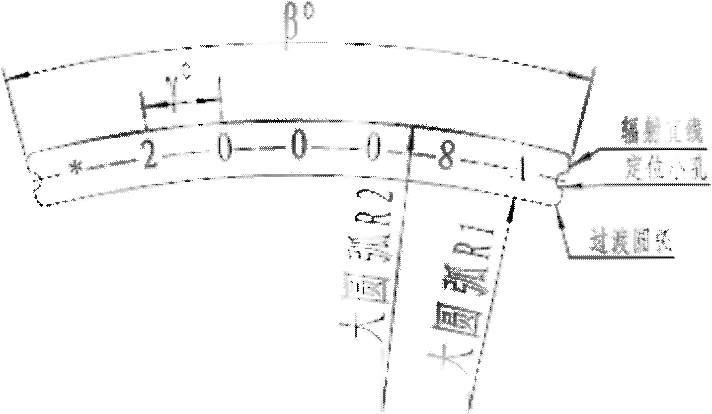
technical field [0001] The invention relates to a fan label forming and shearing device which can be used for cutting a continuously moving metal strip into a fan label, and belongs to the technical field of continuous production of metal labels. Background technique [0002] Metal labels have a large number of applications in the industrial field, with characters (numbers, letters, various symbols and various patterns collectively referred to) on them. The metal label used to print the vulcanized tire number on the surface of the tire requires these characters to be radially arranged along the arc surface, and the shape of the label is fan-shaped (such as figure 1 shown), and requires that this label can be installed and positioned on the tire mold (by figure 1 semi-circular holes on both ends of the label). The patent application No. 200910256568.9 provides a manufacturing method for this character arrangement, and the present invention will provide a label-shaped formin...

Claims


Application Information

Patent Timeline
IPC IPC(8): B23P23/02
Inventor 路长厚陈淑江张建川
Owner SHANDONG UNIV
Why Eureka
Try Eureka