Small-hole square-head circular bead end portion label shearing device and method

A cutting device and rounded corner technology, which is applied in the field of small hole square head rounded corner end label shearing device, can solve the problems that the end shape and structure realization method and technology are not given, and achieve simple structure and convenient use , the effect of high molding precision

Inactive Publication Date: 2020-06-05
SHANDONG UNIV
View PDF2 Cites 0 Cited by
  • Summary
  • Abstract
  • Description
  • Claims
  • Application Information

AI Technical Summary

Problems solved by technology

[0003] In the existing public literature, the Chinese patent No. ZL201010232108.5 provides a fan-shaped label forming and shearing device, and the Chinese patent publication No. CN2628195 provides a special device for cutting metal strips. The device gives the composition of the shearing system, but does not give the realization method and technology of the shape and structure of the end

Method used


Image

  • Small-hole square-head circular bead end portion label shearing device and method
  • Small-hole square-head circular bead end portion label shearing device and method
  • Small-hole square-head circular bead end portion label shearing device and method

Examples


Embodiment 1

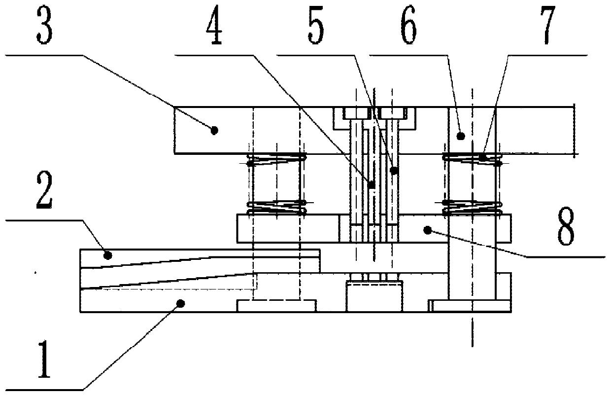
[0039] This embodiment discloses a small hole square head fillet end label shearing device, which includes a die 1, a material guide groove, a small hole punching needle, a reference plate 3, a punch 4, a guide column 5, a spring 6, a press The discharge plate 7, the punch 4 and the small hole punching pin are all connected to the reference plate 3, and the reference plate 3 is connected to the guide column 5; the die 1 is installed on the base, and the punch 4 and the guide column 5 pass through the pressure discharge The gap between the material plate 7, the punch 4, the guide column 5 and the pressing and unloading plate 7 is matched to ensure relative movement, and the spring 6 is socketed with the guide column 5;

[0040] There are two small hole punching needles, and the two small hole punching needles are located on both sides of the punch 4;

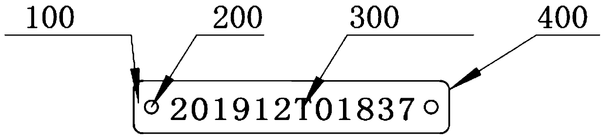
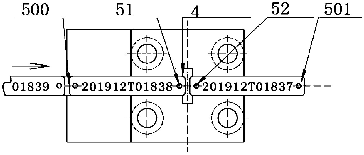
[0041] The end face of the punch 4 forms a blade for cutting the end of the square head rounded semi-circular hole, the blades ...

Embodiment 2

[0058] Embodiment 2 discloses a method for cutting a label at the end of a small hole with a square head and a rounded corner. Using the device for cutting a label at the end of a small hole with a square head and a rounded corner disclosed in Embodiment 1 includes the following steps:

[0059] 1) Import the label to be cut into the chute;

[0060] 2) The label to be cut advances gradually with the drive of the power source;

[0061] 3) Every fixed time t1, or every time the label to be cut moves a certain distance s1, the reciprocating power source starts forward, driving the reference plate 3 to descend in the vertical direction, and the pressing and unloading plate Press the label to be cut first, and the end face of the punch 4 cuts the label to be cut. After the cutting and punching are completed, the reciprocating power source is reversed to drive the reference plate 3 to reset, and the pressing material is unloaded. The sheet pushes the formed label out of the punch. ...


PUM


Abstract

The invention discloses a small-hole square-head circular bead end portion label shearing device and method. A female die, a material guiding groove, small hole punch needles, a datum plate, a male die, a guiding column, a spring and a material pressing and unloading plate are included. The male die and the small hole punch needles are connected to the datum plate, and the datum plate is connectedwith the guiding column. The female die is arranged on the base, the male die and the guiding column penetrate through the material pressing and unloading plate, the male die, the guiding column andthe material pressing and unloading plate are in clearance fit, the relative motion can be guaranteed, and the spring is in cup joint with the guiding column. The two small hole punch needles are arranged and located on the two sides of the male die. Blades for cutting the end portion of a square head circular bead half circular hole are formed on the end face of the male die, the blades on the two sides are symmetrically arranged, and each of the blades on the two sides comprises a top circular bead blade, a linear blade and a bottom circular bead blade which are sequentially connected. By means of the small-hole square-head circular bead end portion label shearing device and method, under the situation of high-efficiency machining is guaranteed, the end portion of the square head circular bead half circular hole of a metal label can still be accurately machined.

Description

technical field [0001] The invention relates to the field of metal label production, in particular to a label cutting device and method for a small hole, square head and rounded corner end label. Background technique [0002] Metal labels have a large number of applications in the industrial field, with characters (numbers, letters, various symbols and various patterns collectively referred to) on them. The metal label used to print the vulcanized tire number on the surface of the tire requires that the end of the label be a square chamfered structure (such as figure 1 , figure 2 shown), and requires small holes to be installed and positioned on the tire mold (by figure 1 , 2 small holes at both ends of the label to achieve). [0003] In the existing public literature, the Chinese patent No. ZL201010232108.5 provides a fan-shaped label forming and shearing device, and the Chinese patent publication No. CN2628195 provides a special device for cutting metal strips. The de...

Claims


Application Information

Patent Timeline
Patent Type & Authority Applications(China)
IPC IPC(8): B65H35/06
CPCB65H35/06
Inventor 路长厚陈淑江张建川
Owner SHANDONG UNIV
Why Eureka
Try Eureka