Clamping device

A clamping device and clamping element technology, which is applied in transportation and packaging, textiles and papermaking, and thin material processing, can solve the problems of yarns not being clamped, yarns not being clamped sufficiently and firmly, etc., to achieve The effect of extending the time window

Active Publication Date: 2013-08-28
SAURER COMPONENTS GMBH
View PDF1 Cites 0 Cited by
  • Summary
  • Abstract
  • Description
  • Claims
  • Application Information

AI Technical Summary

Problems solved by technology

The same applies correspondingly when closing the clamping device, since the clamping device may be closed too early when braking the spindle, as a result, the yarn is not clamped or is not used for holding the yarn during the doffing process. grip fully and firmly

Method used


Image

  • Clamping device
  • Clamping device
  • Clamping device

Examples


Embodiment Construction

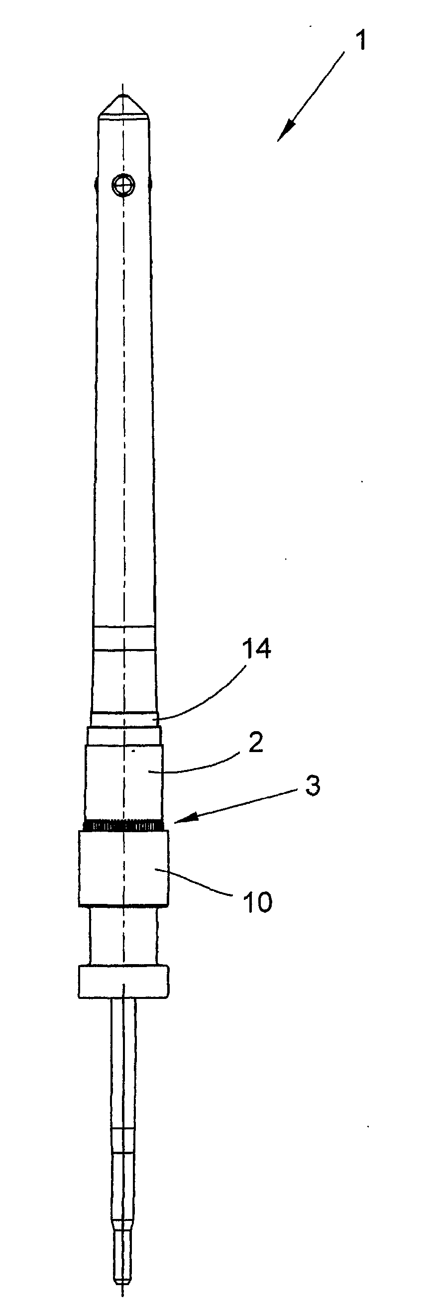
[0023] figure 1 Shown is a spindle top 1 of a spindle of a textile machine, in particular a spinning spindle and a twisting spindle. The spindle upper part 1 has a shank made of metal for receiving a sleeve, not shown, on which the yarn is to be wound into a bobbin. For this purpose, a spinning ring, not shown, is provided on the spindle top 1, which surrounds the spindle top 1 concentrically and on which a traveler turns, which deflects the yarn to the sleeve and Wrapped on sleeve. A driving roller 2 is arranged on the spindle upper part 1, and the spindle upper part 1 can be driven by the driving roller 2 during the operation of the spinning machine.

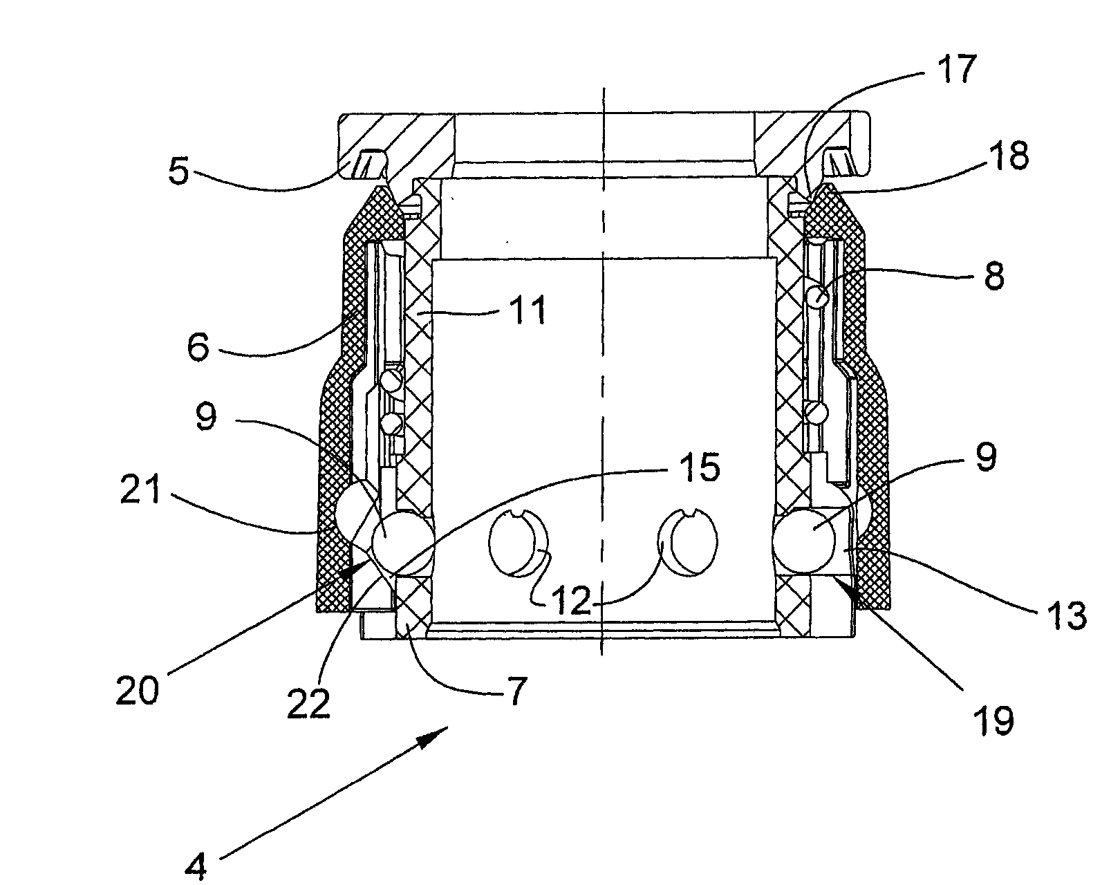
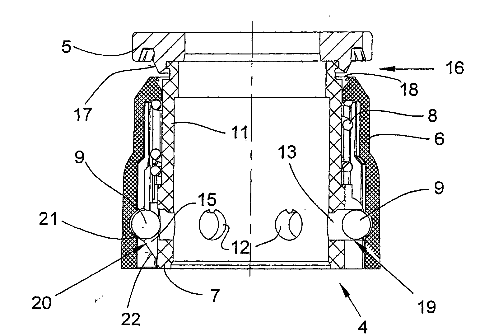
[0024] The drive roller 2 has a cooperating portion 14 for fixing the clamping device 4 according to the invention for clamping the yarn when the produced cop is doffing. The clamping device 4 is actuated by centrifugal force and can be in two positions - a clamped position and an open position, as in figure 2 The yarn is...


PUM


Abstract

The device (4) has half-shells (13, 15) extending in a radial direction and serving for arrangement and guiding of centrifugal force elements (9). One of the half-shells (15) is arranged at an axially slidable clamping element (6). The other half-shell (13) is arranged at a fixedly arranged base element (7). Connecting rods (20) of the former half-shell are formed such that the rods include a different inclination angle in a direction of a longitudinal axis of a spindle upper part based on the former shell than that based on the base element in a direction of the former shell.

Description

technical field [0001] The invention relates to a clamping device for yarn on a spindle of a spinning machine or a twisting machine, the clamping device is arranged on the upper part of the spindle, the clamping device comprises a fixed clamping element and a a movable clamping element that can be moved to and can be pressed against the fixed clamping element by spring force, wherein the movable clamping element can be exerted against the spring force by a spherical centrifugal force element, Said force opposing said spring force causes said movable clamping element to be axially spaced from said fixed clamping element such that a gap between said movable clamping element and said fixed clamping element Clamping gaps are formed between them, and the clamping device has a plurality of half-bearings extending radially, which are used to set and guide the centrifugal force elements, wherein corresponding The half-bearings of the fixedly arranged base elements are provided with c...

Claims


Application Information

Patent Timeline
Patent Type & Authority Patents(China)
IPC IPC(8): D01H1/38D01H1/40
CPCB65H2402/25B65H65/00B65H2701/31D01H1/38B65H2402/20
Inventor 戈特弗里德·施陶登迈尔
Owner SAURER COMPONENTS GMBH
Why Eureka
Try Eureka