Method for measuring and calculating binocular vision displacement measurement errors and measuring system

A technology of displacement measurement and binocular vision, applied in measurement devices, instruments, optical devices, etc., can solve problems such as inability to calculate errors, inability to accurately calculate error values, and large differences in measurement results.

Inactive Publication Date: 2010-12-01
BEIJING INSTITUTE OF TECHNOLOGYGY
View PDF4 Cites 14 Cited by
  • Summary
  • Abstract
  • Description
  • Claims
  • Application Information

AI Technical Summary

Problems solved by technology

[0005] The above-mentioned binocular vision measurement error is not a binocular vision displacement measurement error. The two errors are not exactly the same. Moreover, the calculation method of the mathematical model error often does not consider the specific measurement environment, and the binocular vision measurement method is very sensitive to ambient light. , the measurement results under different ambient light effects are very different, so the mathematical model method cannot calculate the error in the specific measurement environment
In addition, the mathematical model error calculation method can reflect the change trend of measurement error and can be used as a basis for guiding the selection of measurement parameters, but it cannot accurately calculate the error value
Therefore, so far, there is no method and corresponding measurement system for measuring the binocular vision displacement measurement error in the field environment.

Method used


Image

  • Method for measuring and calculating binocular vision displacement measurement errors and measuring system
  • Method for measuring and calculating binocular vision displacement measurement errors and measuring system
  • Method for measuring and calculating binocular vision displacement measurement errors and measuring system

Examples


Embodiment Construction

[0012] In order to make the technical problems, technical solutions and advantages to be solved by the present invention clearer, the following will describe in detail with reference to the drawings and specific embodiments.

[0013] The invention provides a method for measuring and calculating the binocular vision displacement measurement error in the field environment. This method is specifically described below.

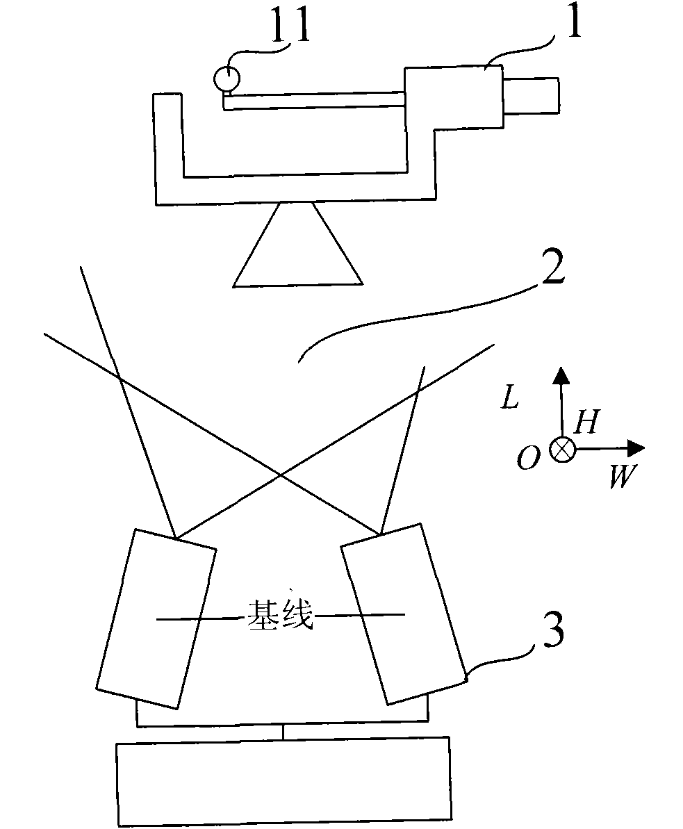
[0014] First, if figure 2 As shown, the marker 11 is set on the head of the standard measuring tool 1. The standard measuring tool 1 can be a standard measuring tool such as a screw micrometer or a vernier caliper. The standard measuring tool 1 in this embodiment takes a screw micrometer as an example. The marker 11 is a specially coated spherical part, which is very sensitive to light, so that the marker 11 can be clearly distinguished from its background. There are many ways to set the marker 11 on the ruler head of the standard measuring tool 1. For example,...


PUM


Abstract

The invention provides a method for measuring and calculating binocular vision displacement measurement errors and a measuring system based on a standard measuring tool (a screw micrometer or a vernier caliper). The method comprises the following steps of: arranging a marker on a meter head of the standard measuring tool; parallelly arranging the standard measuring tool in three coordinate axis directions in a three-dimensional coordinate system of a stereo space respectively, regulating the standard measuring tool to move the marker together with the meter heads in the three coordinate axis directions respectively and acquiring actual values of displacement of the marker; and calculating an arithmetic mean value of absolute values of the difference between the actual values and measured values of the displacement to acquire the displacement measurement errors in the three coordinate axis directions respectively, and calculating the displacement measurement errors in the three coordinate axis directions to acquire errors in an entire measurement range. The system comprises the standard measuring tool (the screw micrometer or the vernier caliper) and a binocular vision measurement device.

Description

technical field [0001] The present invention relates to a measurement method and a measurement system for binocular vision displacement measurement error, and more specifically, to a method and device for measuring and calculating binocular vision displacement measurement error in a specific measurement environment. Background technique [0002] Binocular vision technology is an important technology in the field of computer vision. Binocular vision technology can reconstruct the coordinates of a point in space through the internal and external parameters of two cameras and the coordinates of corresponding points on the imaging plane of the two cameras. like figure 1 As shown, I 1 and I 2 are the imaging planes of the left and right cameras, C 1 and C 2 are the optical centers of the left and right cameras respectively, there is a point M on a certain plane π in space, and the point M is at I 1 and I 2 The projected points on are respectively P 1 and P 2 (i.e., optica...

Claims


Application Information

Patent Timeline
Patent Type & Authority Applications(China)
IPC IPC(8): G01B11/03
Inventor 刘检华宁汝新王小寅
Owner BEIJING INSTITUTE OF TECHNOLOGYGY
Why Eureka
Try Eureka