
Method and system for calibrating external parameters based on camera and three-dimensional laser radar

A camera coordinate system, three-dimensional laser technology, applied in the field of cameras and three-dimensional lidar, can solve the problems of not considering the error of the intermediate quantity, not considering the measurement error, the calibration of the external parameter rotation matrix R is not accurate enough, etc., to achieve accurate results, The effect of improving accuracy

Inactive Publication Date: 2010-04-28
BEIJING INSTITUTE OF TECHNOLOGYGY
View PDF0 Cites 55 Cited by
  • Summary
  • Abstract
  • Description
  • Claims
  • Application Information

AI Technical Summary

Problems solved by technology

[0009] Ranjith Unnikrishnan used the checkerboard as the target to calibrate the external parameters of the camera and 3D lidar, and globally optimized the results, and achieved good results, but this method did not consider the error of the intermediate quantity calculated from different target planes Impact
[0010] The various methods mentioned above do not take into account the accurate estimation of the measurement error in the calibration results, which leads to the inaccurate calibration of the external parameter rotation matrix R

Method used


Image

  • Method and system for calibrating external parameters based on camera and three-dimensional laser radar
  • Method and system for calibrating external parameters based on camera and three-dimensional laser radar
  • Method and system for calibrating external parameters based on camera and three-dimensional laser radar

Examples


Embodiment Construction

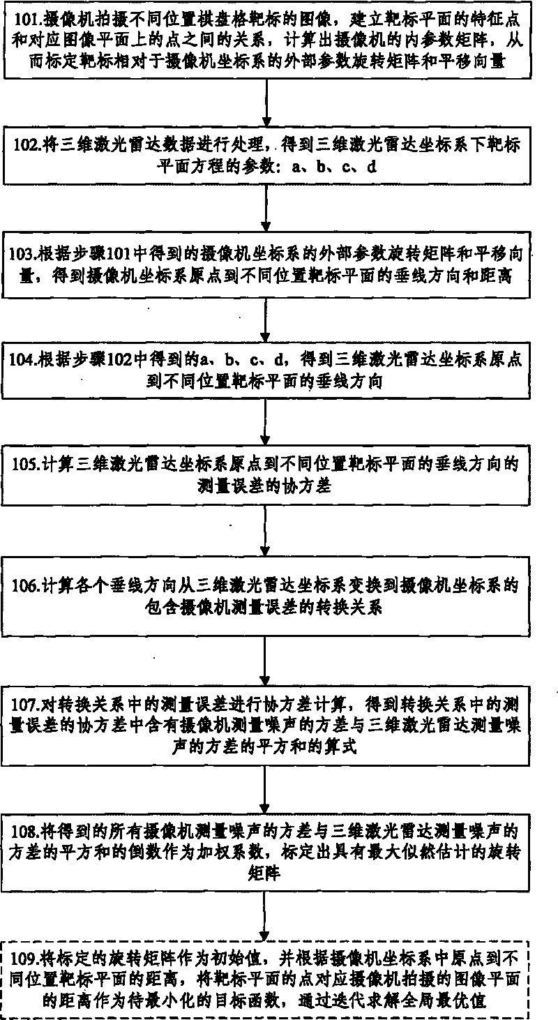
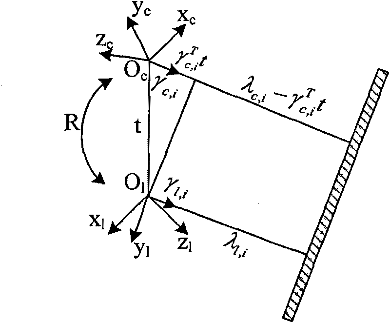
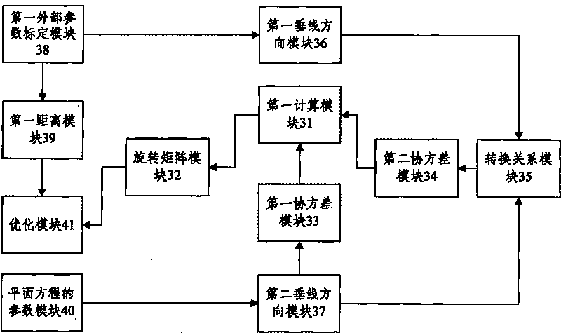
[0043] The basic idea of ​​the present invention is: according to the covariance of the measurement error from the origin of the three-dimensional laser radar coordinate system to the vertical direction of the target plane at different positions, and the measurement error in the conversion relationship of the vertical direction from the three-dimensional laser radar coordinate system to the camera coordinate system The covariance of the measurement error in the conversion relationship contains the formula of the sum of the squares of the variance of the camera measurement noise and the variance of the three-dimensional laser radar measurement noise. The reciprocal of the sum of squared variances is used as a weighting coefficient to calibrate the rotation matrix with maximum likelihood estimation.

[0044] The present invention will be further described in detail below in conjunction with the accompanying drawings and specific embodiments.

[0045] The present invention realiz...


PUM


Abstract

The invention discloses a method for calibrating external parameters based on a camera and a three-dimensional laser radar, which comprises the following steps: according to a covariance of measurement errors in the perpendicular line direction from a three-dimensional laser radar coordinate system origin to different position target planes and a covariance of measurement errors in a conversion relationship from a three-dimensional laser radar coordinate system to a camera coordinate system in the perpendicular line direction, acquiring an equation of a quadratic sum of the variance including the variance of the camera measurement noise and the variance of the three-dimensional laser radar measurement noise in the covariance of the measurement errors in the conversion relationship; and calibrating a rotation matrix with maximum likelihood estimate by using the reciprocal of the quadratic sum of the variances of all obtained measurement noise as a weighting coefficient. The invention also discloses a system for calibrating the external parameters based on the camera and the three-dimensional laser radar at the same time. The effect of the measurement errors on the rotation matrix to be calibrated is taken into consideration during calibrating, and the algorithm of the maximum likelihood estimate is adopted for the measurement errors in the calibrated result of the rotation matrix, so the calibrating result is more accurate.

Description

technical field [0001] The invention relates to camera and three-dimensional laser radar technology, in particular to an external parameter calibration method and system based on camera and three-dimensional laser radar. Background technique [0002] At present, due to the wide detection range and rich signals of visible light cameras, they have been widely used in the process of vehicle environment perception, but they are easily affected by external factors, and there are problems such as missing targets and blurring. In recent years, with the gradual development of lidar, the use of lidar for ranging has been widely used. Lidar has the advantages of simple ranging principle, high measurement accuracy, fast speed, and is not affected by external lighting conditions. The distance information and the color information of the camera are highly complementary, so the fusion of the two information has become a research hotspot today. This fusion method can be applied to many oc...

Claims


Application Information

Patent Timeline
IPC IPC(8): G01S7/497G06T7/00
Inventor 付梦印杨建孟红
Owner BEIJING INSTITUTE OF TECHNOLOGYGY
Learn More