
Encoder zero-crossing detecting device and detecting method

A zero-point detection and encoder technology, applied in the direction of the instrument, can solve the problems of loose coupling, no zero-point detection device, angular phase deviation or running, etc., achieve automatic zero point position, convenient installation and debugging, and work phase Control the exact effect

Active Publication Date: 2010-12-01
YANGZHOU HAILI PRECISION MACHINERY MFG
View PDF0 Cites 12 Cited by
  • Summary
  • Abstract
  • Description
  • Claims
  • Application Information

AI Technical Summary

Problems solved by technology

[0002] The existing coupling transmission is prone to loosening, and the encoder control has drift phenomenon, but there is no zero point detection device at present
The existing structure is to find the zero point through manual debugging, start the machine to rotate the main eccentric shaft, and find out the working zero point of the rotary encoder as the origin of reference, which is inaccurate and inconvenient
The rotary encoder of the original mechanism often produces angular phase deviation or running, sometimes it is impossible to know, and it is only discovered after the phase of each part of the machine is abnormal

Method used


Image

  • Encoder zero-crossing detecting device and detecting method
  • Encoder zero-crossing detecting device and detecting method

Examples


Embodiment Construction

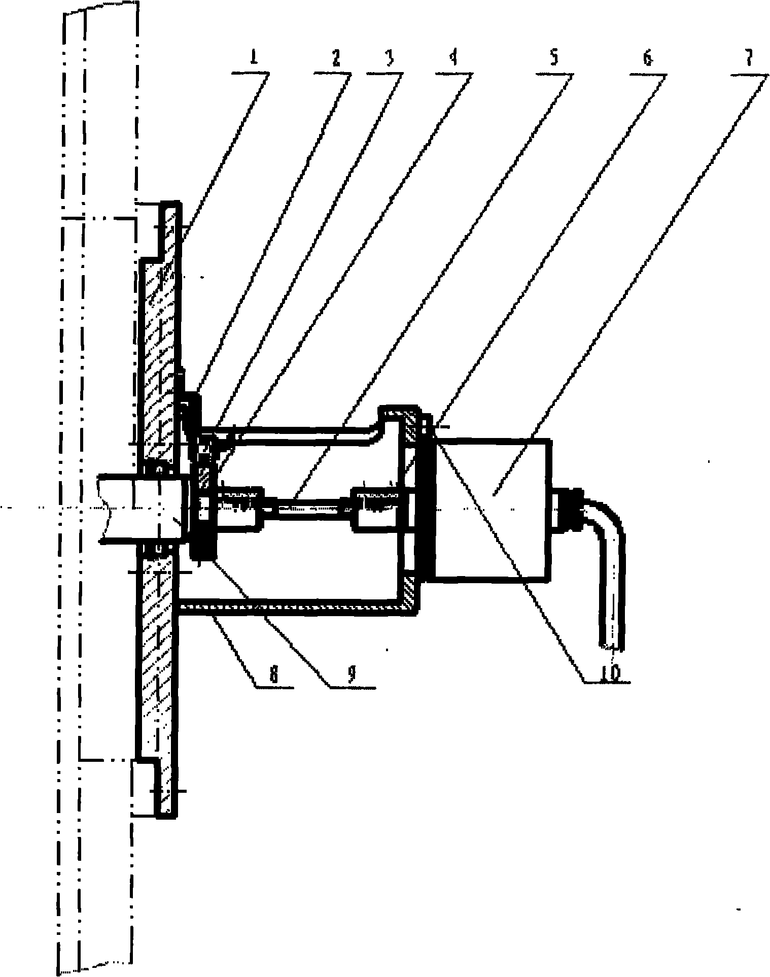
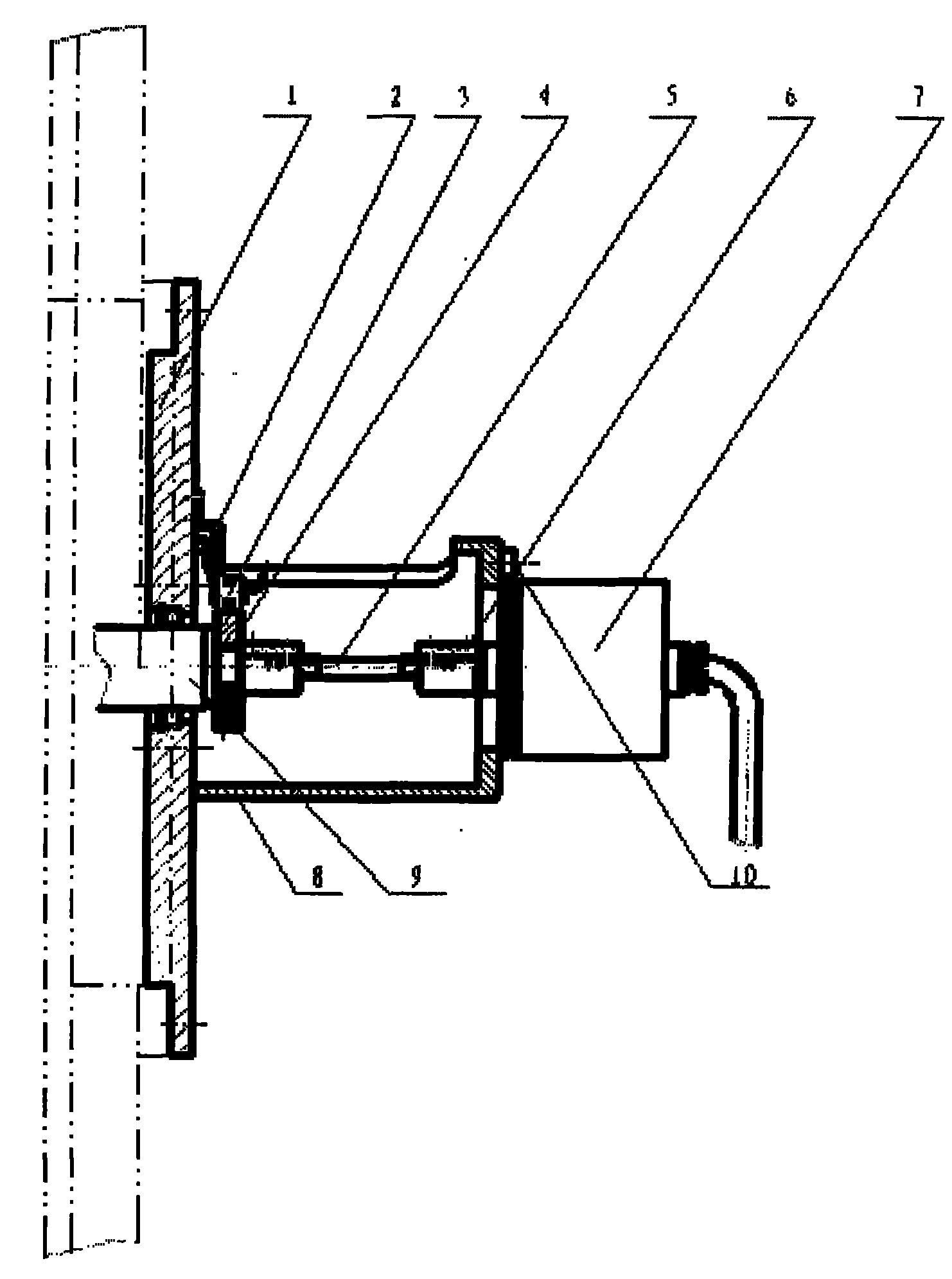
[0013] 1, an encoder zero point detection device of the present invention includes an encoder connecting flange 1, a sensor bracket 2, a detection sensor 3, a detection cam 4, a connecting shaft 5, a shaft coupling 6, a rotary encoder 7, an encoder Device connection seat 8, output shaft 9, fixed pressure plate 10; one end of the detection cam 4 is connected with the output shaft 9, and the detection sensor 3 used to detect the cam phase is arranged on the outside of the detection cam 4, and the sensor passes through the sensor bracket 2 and The encoder connection flange 1 is fixed on the machine body, the other end of the detection cam 4 is connected with the rotary encoder 7 through the connecting shaft 5 and the coupling 6, and the encoder is fixed on the encoder through the fixed pressure plate 10 and the encoder connection seat 8. The device is connected to flange 1.

[0014] A kind of detection method based on encoder zero detection device of the present invention compris...


PUM


Abstract

The invention relates to an encoder zero-crossing detecting device. The device comprises an encoder connecting flange, a sensor holder, a detecting sensor, a detecting cam, a connecting shaft, a coupler, a rotary encoder, an encoder connecting base, an output shaft and a fixing plate, wherein one end of the detecting cam is connected with the output shaft; the detecting sensor used for detecting the phase of the cam is arranged outside the detecting cam; the sensor is fixed on the engine body through the sensor holder and the encoder connecting flange; the other end of the detecting cam is connected with the rotary encoder through the connecting shaft and the coupler; and the encoder is fixed on the encoder connecting flange through the fixing plate and the encoder connecting base. By using the encoder zero-crossing detecting device, the work phase of machine can be controlled more accurately without any position drift phenomenon.

Description

technical field [0001] The invention relates to a zero point phase detection device, in particular to an encoder zero point detection device. Background technique [0002] The existing coupling transmission is prone to loosening, and the encoder control has drift phenomenon, but there is no zero point detection device at present. The existing structure is to find the zero point through manual debugging, start the machine to rotate the main eccentric shaft, and find out the working zero point of the rotary encoder as the origin of reference, which is inaccurate and inconvenient. The rotary encoder of the original mechanism often produces angular phase deviation or running, sometimes it is impossible to know, and it is only discovered after the phase of each part of the machine is abnormal. Contents of the invention [0003] The technical problem solved by the present invention is to provide an encoder zero point detection device and a detection method thereof. [0004] Th...

Claims


Application Information

Patent Timeline
IPC IPC(8): G01D18/00
Inventor 冯金玉闫德亮
Owner YANGZHOU HAILI PRECISION MACHINERY MFG
Learn More