Method for reactive ion beam etching of blazed convex grating

A technology of ion beam etching and convex grating, which is applied in the direction of diffraction grating, photographic process of pattern surface, optics, etc., and can solve the problems of immature research on grating manufacturing technology

Inactive Publication Date: 2010-12-01
UNIV OF SHANGHAI FOR SCI & TECH
View PDF4 Cites 6 Cited by
  • Summary
  • Abstract
  • Description
  • Claims
  • Application Information

AI Technical Summary

Benefits of technology

The technical effect that this new technology can improve upon existing methods for producing materials or products by improving their properties such as strengths, durability, etc., without adding extra steps like heat treatment or other treatments.

Problems solved by technology

Technological Problem: In this patented technical problem addressed by the National Aeronautics Administration (NASA) for producing high performance cameras or other devices called Optrolux® Structures Imaging Spectrum System(OIS). However, current methods have limitations making them difficult to make very fine lenses at specific wavelength ranges due to difficulties associated with creation of these types of structures through traditional processes like cutting and polishing materials.

Method used


Image

  • Method for reactive ion beam etching of blazed convex grating
  • Method for reactive ion beam etching of blazed convex grating
  • Method for reactive ion beam etching of blazed convex grating

Examples


Embodiment Construction

[0023] The specific implementation manner of the present invention will be further described in detail below in conjunction with the accompanying drawings and examples, but the protection scope of the present invention should not be limited thereby.

[0024] The design steps of the blazed convex grating reactive ion beam etching method are:

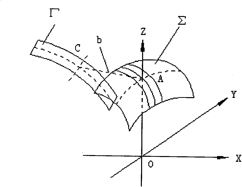
[0025] 1. Placement of convex grating mask quartz substrate. A convex grating mask quartz substrate with a sinusoidal groove shape is placed on a rotary table, and the center of the sphere is on the rotary axis of the rotary table. The plane where the reticle lines are located at the apex of the convex grating mask passes through the axis of rotation, and the planes where the other reticle lines are located are parallel to the axis of rotation.

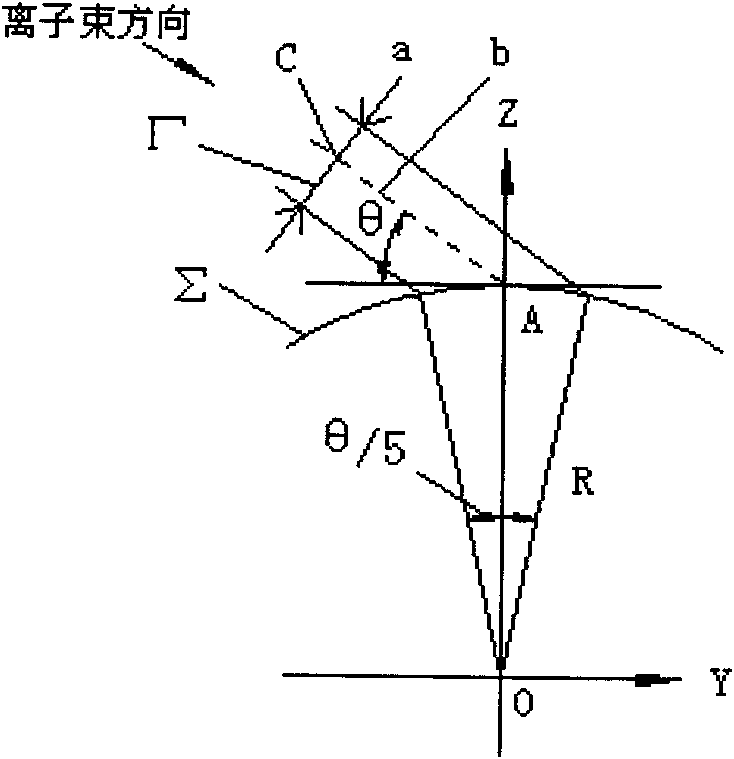
[0026] 2. If the spherical radius of the quartz substrate of the convex grating mask is R, and the blaze angle of the blazed convex grating to be made is θ, then the direction of the ion beam an...


PUM


Abstract

The invention discloses a method for a reactive ion beam etching (RIBE) of a blazed convex grating, which comprises the following steps: step one: placing a masking quartz substrate of the convex grating; step two: ensuing an angle of the ion beam direction and a groove at the peak of the grating to be theta if the spherical radius of the masking quartz substrate of the convex grating is R and the blazed angle of the blazed convex grating is theta; step three: manufacturing an etching slit; step four: placing the slit; and step five: etching the convex grating. The technical scheme of the invention adopts a subsection etching method, namely, a subsection ion beam etching is carried out on the masking quartz substrate of the convex grating with a sine groove shape, so that the relative error of the blazed angle of the blazed convex grating which is etched is 0.1 in theory.

Description


Claims


Application Information

Patent Timeline
Owner UNIV OF SHANGHAI FOR SCI & TECH
Why Eureka
Try Eureka