
Connector for optical sensor and substrate, method for manufacturing optical sensor
A technology of optical sensor and manufacturing method, applied in the input/output process of instruments, data processing, electrical digital data processing, etc., capable of solving problems such as difficult control, time-consuming yield, cost increase of optical touch control system, etc.
- Summary
- Abstract
- Description
- Claims
- Application Information
AI Technical Summary
Problems solved by technology
Method used
Image

Examples
Embodiment Construction
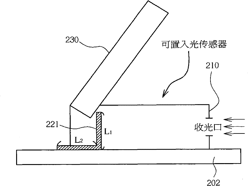
[0037] The invention provides a connector capable of connecting an optical sensor and a substrate. The connector provided by the invention can transpose the light sensor so that the light receiving direction of the light sensor is parallel to the substrate. In this way, by using the connector provided by the present invention, the light sensor can be disposed on the substrate, and the light receiving direction of the light sensor can be kept parallel to the substrate.
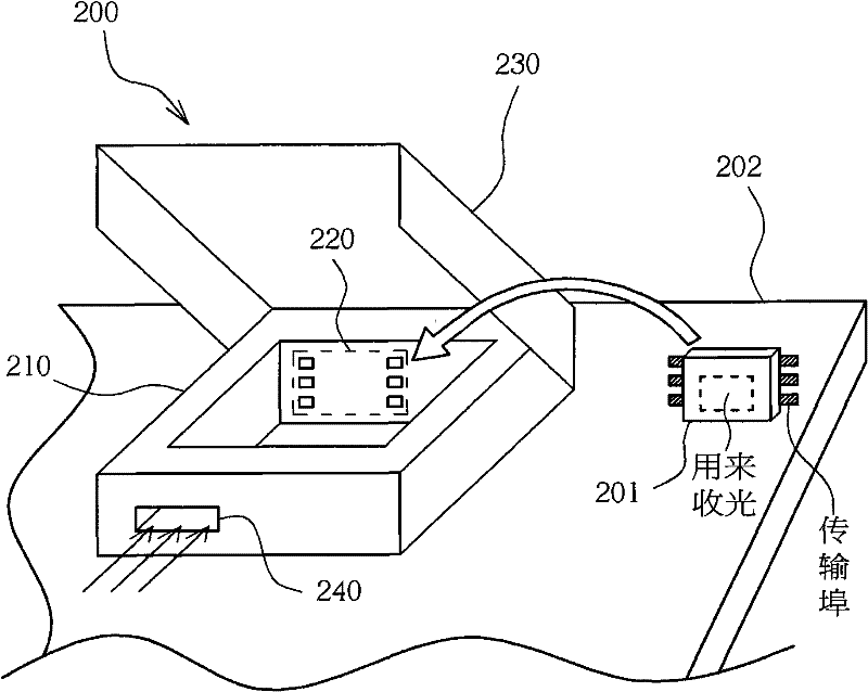
[0038] Please refer to figure 2 . figure 2 It is a schematic diagram illustrating the connector 200 according to the first embodiment of the present invention. exist figure 2 Among them, the connector 200 is disposed on the substrate 202 . The substrate 202 is a transparent substrate (such as a glass substrate or ITO glass). The connector 200 includes a body 210 , a connection port 220 , an upper cover 230 , and a light receiving port 240 . There is enough space in the body 210 for accommodating a light...
PUM
 Abstract
Description
Claims
Application Information