
Fuel cell system module

A fuel cell system and fuel cell technology, applied in the field of aircraft, can solve problems such as long-term grounding of aircraft, and achieve the effects of weight and fuel saving, increased payload capacity, and efficient operation

Active Publication Date: 2010-12-01
AIRBUS OPERATIONS GMBH
View PDF5 Cites 0 Cited by
  • Summary
  • Abstract
  • Description
  • Claims
  • Application Information

AI Technical Summary

Problems solved by technology

However, in the case of fuel cell systems for aircraft, it is a problem that maintenance or repair work on the fuel cell system may lead to long immobilisation times of the aircraft

Method used


Image

  • Fuel cell system module
  • Fuel cell system module
  • Fuel cell system module

Examples


Embodiment Construction

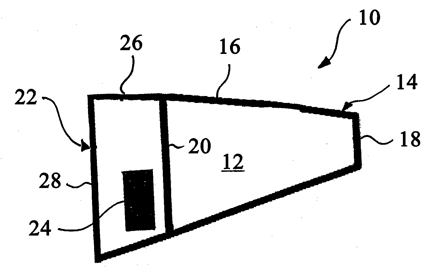
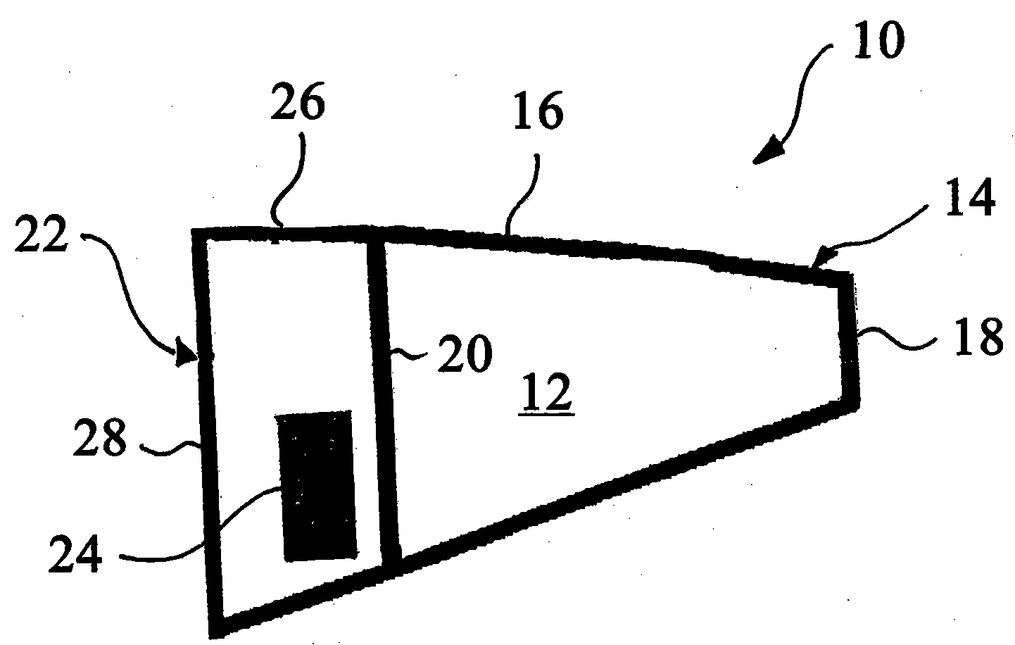
[0020] figure 1 The illustrated fuel cell system module 10 is formed as an aircraft tail boom and includes a fuel tank 12 adapted to store hydrogen at high pressure. The fuel tank 12 has a fuel tank housing 14 with an outer side 16 , a rear boundary 18 and a separation surface 20 . The fuel cell system module 10 further includes a fuel cell system case 22 which adjoins the fuel tank case 14 and in which the peripheral components of the fuel cell system and the fuel cell 24 are accommodated. . The fuel cell system housing 22 includes an outer side 26 and a nose side interface 28 .

[0021] In the region of the nose-side interface 28 of the fuel cell system housing 22, the fuel cell system module 10 is provided with fastening means, such as figure 2 As shown, the fastening device is designed to modularly connect the fuel cell system module 10 to the fuselage section 30 of the aircraft 32 . The fastening device can be formed as a threaded connection or a riveted connection, ...


PUM


Abstract

A fuel cell system module (10) for use in an aircraft (32) comprises at least one fuel cell system component (12, 22, 24). The fuel cell system module (10) can be connected in a modular manner to a fuselage section (30) of the aircraft (32). A housing element (16, 26) of the fuel cell system module (10) is designed to form a section of an external skin (34) of the aircraft (32) when the fuel cellsystem module (10) is in the connected state with the fuselage section (30) of the aircraft (32).

Description

technical field [0001] The invention relates to a fuel cell module for an aircraft, a set of such fuel cell system modules and an aircraft equipped with such a fuel cell system module. Background technique [0002] Fuel cell systems are capable of generating electric current with low emissions and high efficiency. Therefore, efforts are currently also being made to use fuel cell systems in aircraft structures to generate the electrical power required on board. For example, it is conceivable to use a fuel cell system to replace the generator currently used as an on-board power source and driven by the main engine or the aircraft's auxiliary power unit (APU). In addition, the fuel cell system can also be used as an emergency power source for the aircraft and replace the ram air turbine (RAT) that has been used as the emergency power unit. However, in the case of fuel cell systems for aircraft, it is a problem that maintenance or repair work on the fuel cell system may lead t...

Claims


Application Information

Patent Timeline
Patent Type & Authority Applications(China)
IPC IPC(8): B64D27/24B64D41/00
CPCY02T50/44Y02T90/32H01M2250/20B64D41/00H01M8/2475Y02T90/36Y02E60/50B64D2041/005Y02T50/40Y02T90/40
Inventor 安德力斯·韦斯滕贝格尔奥利弗·托马施韦斯基尤莉卡·布莱勒
Owner AIRBUS OPERATIONS GMBH
Learn More