
Safety device of electric iron rolling door

A technology for safety devices and iron rolling doors, which is applied in door/window protection devices, windows/doors, building components, etc. It can solve problems such as rapid falling of rolling door pieces, rapid sliding of rolling door pieces, inconvenient operation and maintenance, etc. To achieve the effect of ensuring safety

Inactive Publication Date: 2010-12-08
GOLDEN MOUNTAIN MACHINERY
View PDF0 Cites 2 Cited by
  • Summary
  • Abstract
  • Description
  • Claims
  • Application Information

AI Technical Summary

Problems solved by technology

[0003] The existing electric rolling door machine hides a potential crisis, and the reduction gear in the motor 91 is prone to factors such as gear chipping or wear and brake failure, so that the rolling door piece 95 of the existing electric rolling door machine slides rapidly, causing personal injury or property damage. damage
[0004] Traditionally, in order to overcome the above-mentioned problems, the various components of the electric rolling door machine are enlarged and thickened to deal with it. However, this results in a waste of materials and is not easy to produce, and the large and heavy electric rolling door machine is more difficult to maintain.
[0005] Not only that, there is no guarantee that the rolling door will not fall off with thick materials. Although it may have a long service life, the danger of the above-mentioned rolling door sheet 95 falling rapidly may occur if the maintenance is forgotten over time. Sometimes they don’t pay attention to the safety of the electric rolling door machine, not to mention that the electric rolling door machine is set several meters above the head, it is easy to forget about regular maintenance and inspection, and it will increase the weight of the electric rolling door machine and make it difficult to operate. and maintenance is more inconvenient

Method used


Image

  • Safety device of electric iron rolling door
  • Safety device of electric iron rolling door
  • Safety device of electric iron rolling door

Examples


Embodiment Construction

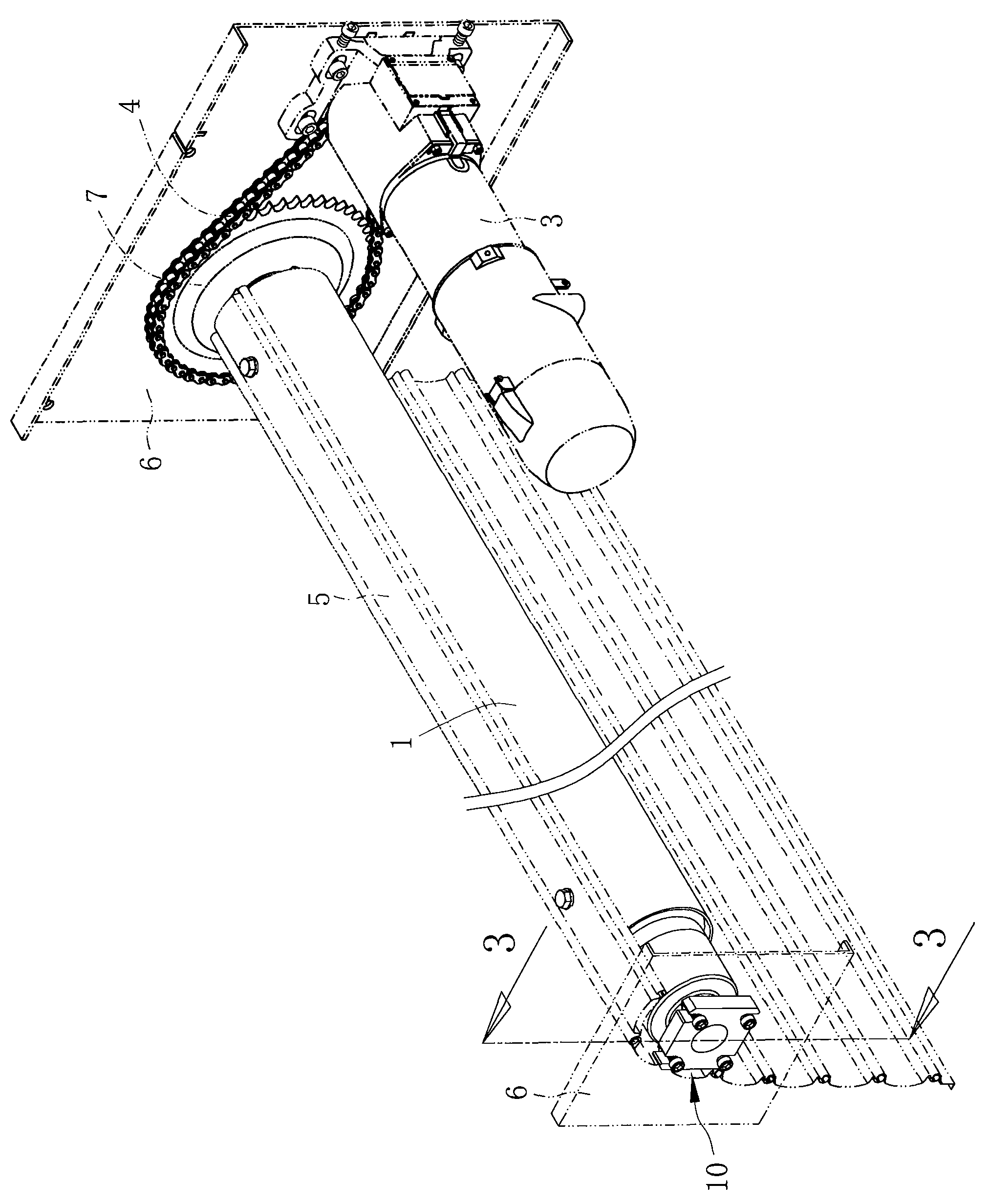
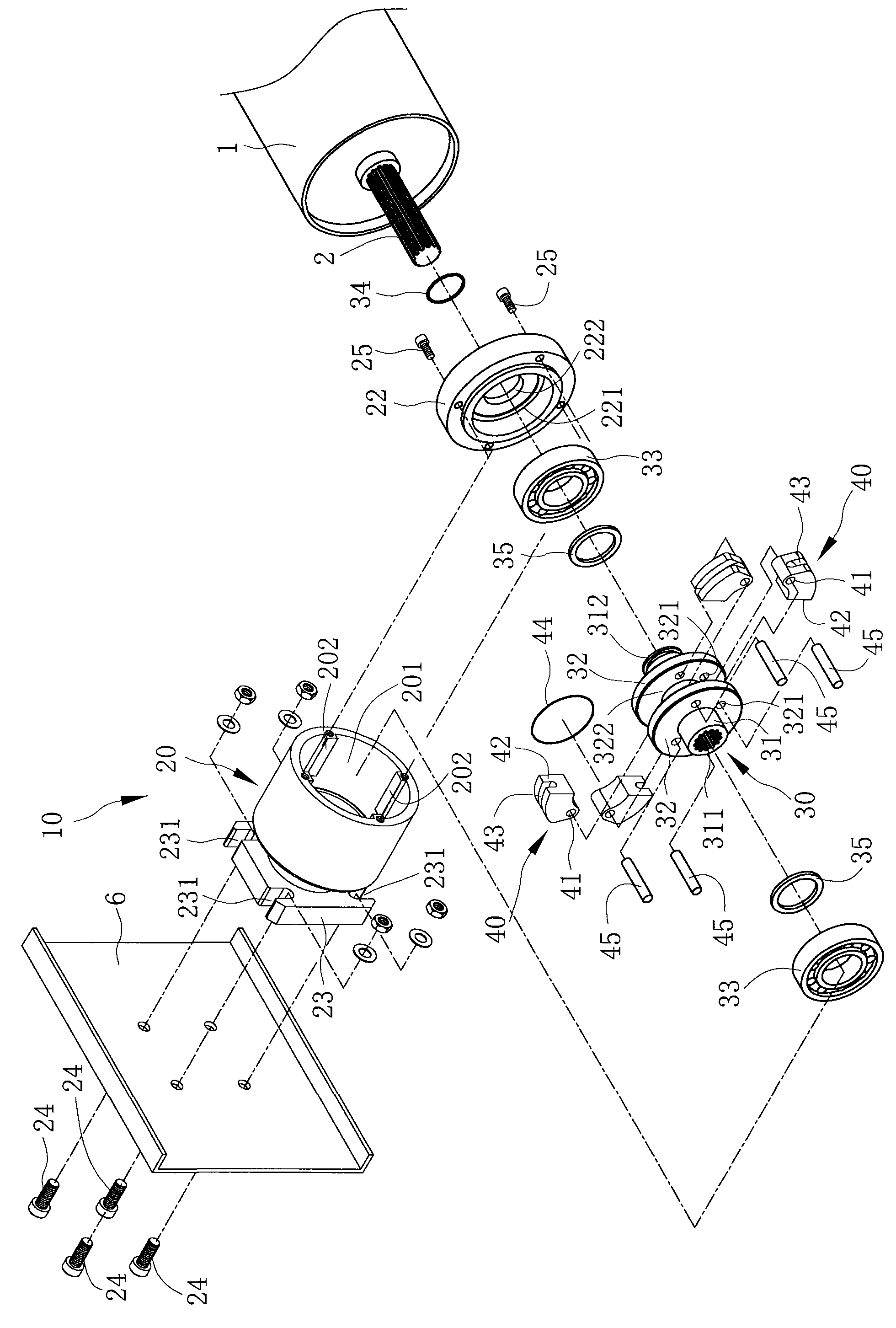
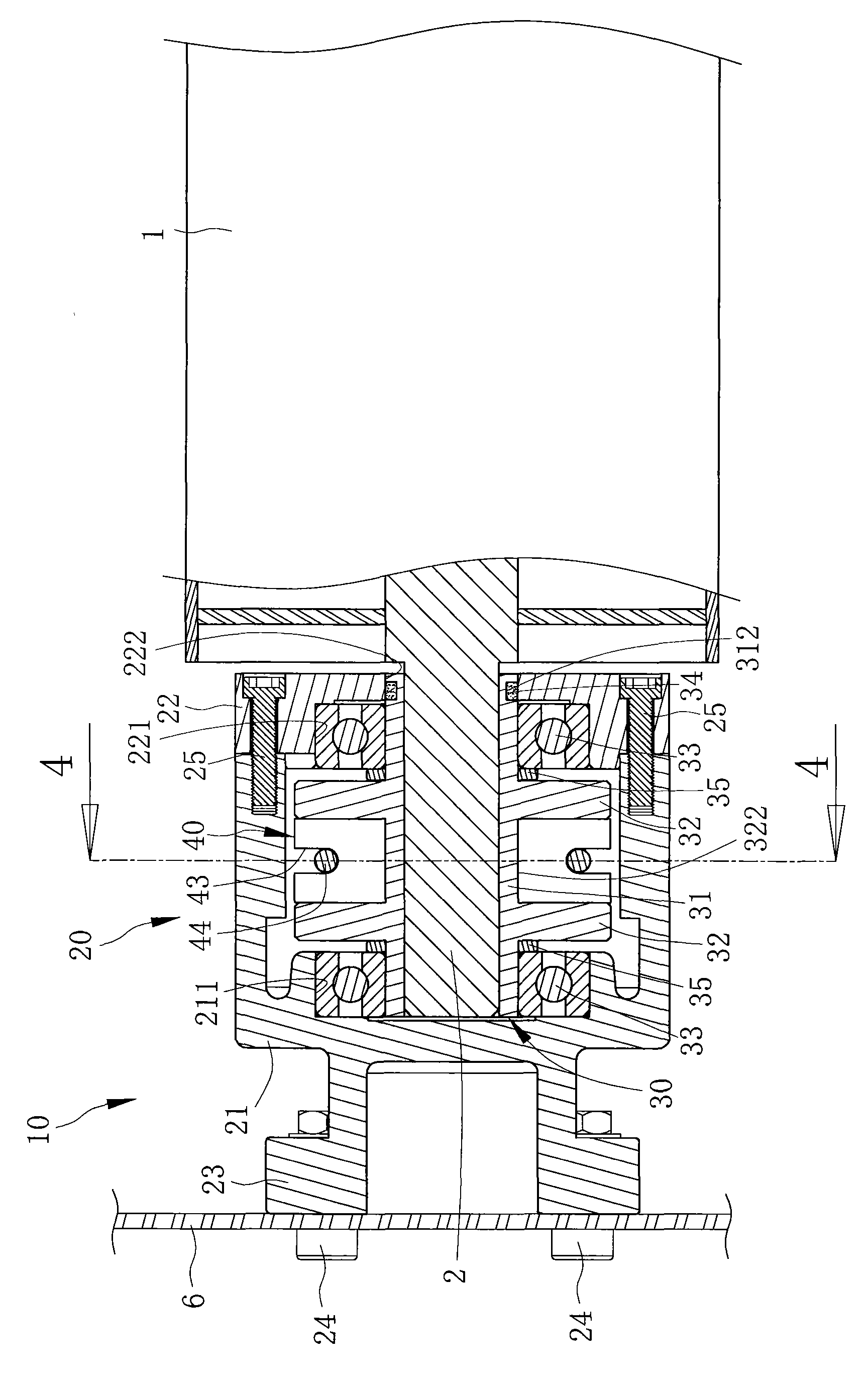
[0027] refer to Figure 1 to Figure 3 , the safety device 10 of the present invention is connected to the shaft 2 of the rolling bar 1, in case the chain 4 between the rolling bar 1 and the rolling door machine 3 breaks due to wear and tear, the safety device 10 will function to block the rolling bar 1, Prevent accidents caused by the rapid drop of the rolling door sheet 5, and ensure the safety of life and property.

[0028] Please cooperate with the reference image 3 The frame plate 6 is equipped with a rolling door machine 3 and a rolling bar 1 , the shaft 2 of the rolling bar 1 is combined with a toothed plate 7 at one end, and the rolling bar 1 and the toothed plate 7 can generate a rotational relationship with respect to the frame plate 6 . The door rolling machine 3 is provided with a motor (not shown) that can be electrically controlled, and the motor drives a gear (not shown) that is pivotally connected to the frame plate 6, so that the gear can be driven by the mot...


PUM


Abstract

The invention discloses a safety device of an electric iron rolling door, comprising a casing, a base and at least one clamping block, wherein an accommodation space is formed in the casing; the inner surface of the casing is provided with at least one stopping part convex inwards in radial direction; the base is provided with a shaft part and is pivoted in the casing; teeth are arranged in the shaft part for being matched with a shaft lever of a rolling bar, so that the base can synchronously rotate with the rolling bar; the outer surface of the shaft part of the base is provided with at least one limiting part extending towards in radial time; one end of the clamping block is pivoted on the limiting part of the base and is tightened on the shaft part of the base through an elastic piece; once a chain between the rolling bar and the rolling door machine is broken due to the wear, the safety device connected to the shaft lever of the roller bar can generate the action to stop the rolling bar, prevent a rolling door sheet from quickly falling off to cause an accident, thereby ensuring the safety of life and property.

Description

technical field [0001] The invention designs an electric iron rolling door, especially a safety device for the electric iron rolling door connected to a shaft rod of a rolling bar. Background technique [0002] refer to Figure 7 , is a traditional electric rolling door machine, which includes a base 90, the base 90 has a first end and a second end, and the first end of the base 90 is provided with a drive wheel connected to the motor 91 (not shown in the figure shown), and the second end of the base 90 is provided with a driven wheel 93 that can be combined with the rolling bar 92, and the driving wheel and the driven wheel 93 are linked by a chain 94. [0003] The existing electric rolling door machine hides a potential crisis, and the reduction gear in the motor 91 is prone to factors such as gear chipping or wear and brake failure, which makes the rolling door piece 95 of the existing electric rolling door machine slip rapidly, causing personal injury or property damage....

Claims


Application Information

Patent Timeline
Patent Type & Authority Applications(China)
IPC IPC(8): E06B9/56E06B9/80
Inventor 洪金山
Owner GOLDEN MOUNTAIN MACHINERY
Learn More