Wiring circuit base plate

A technology for wiring circuit substrates and conductive substrates, which is applied in the field of wiring circuit substrates, can solve problems such as differential signal transmission errors, and achieve the effect of preventing transmission errors

Inactive Publication Date: 2010-12-08
NITTO DENKO CORP
View PDF3 Cites 2 Cited by
  • Summary
  • Abstract
  • Description
  • Claims
  • Application Information

AI Technical Summary

Problems solved by technology

Therefore, there is a problem that a transmission error of the differential signal of the write conductors W1, W2 and a transmission error of the differential signal of the read conductors R1, R2 occur.

Method used


Image

  • Wiring circuit base plate
  • Wiring circuit base plate
  • Wiring circuit base plate

Examples


no. 1 approach

[0050] (1-1) Structure of the suspension board

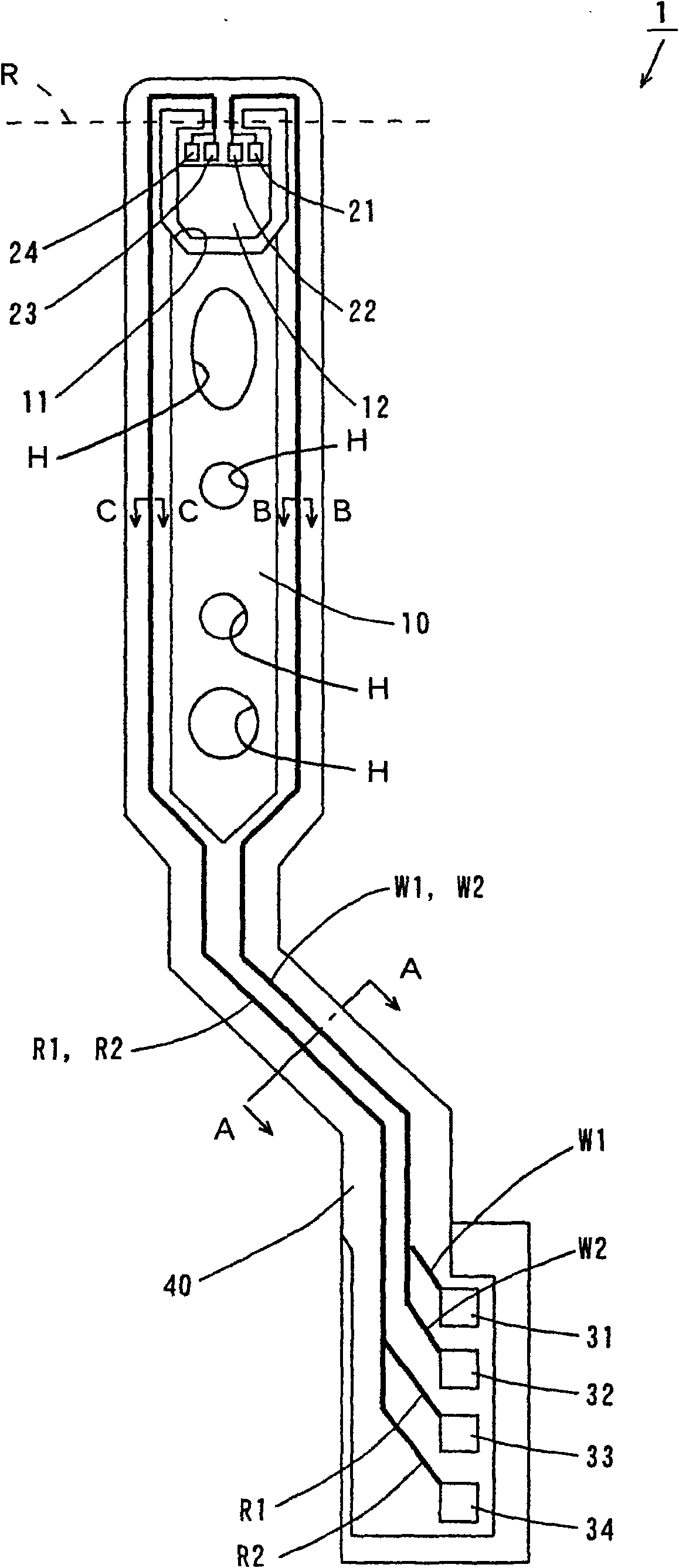
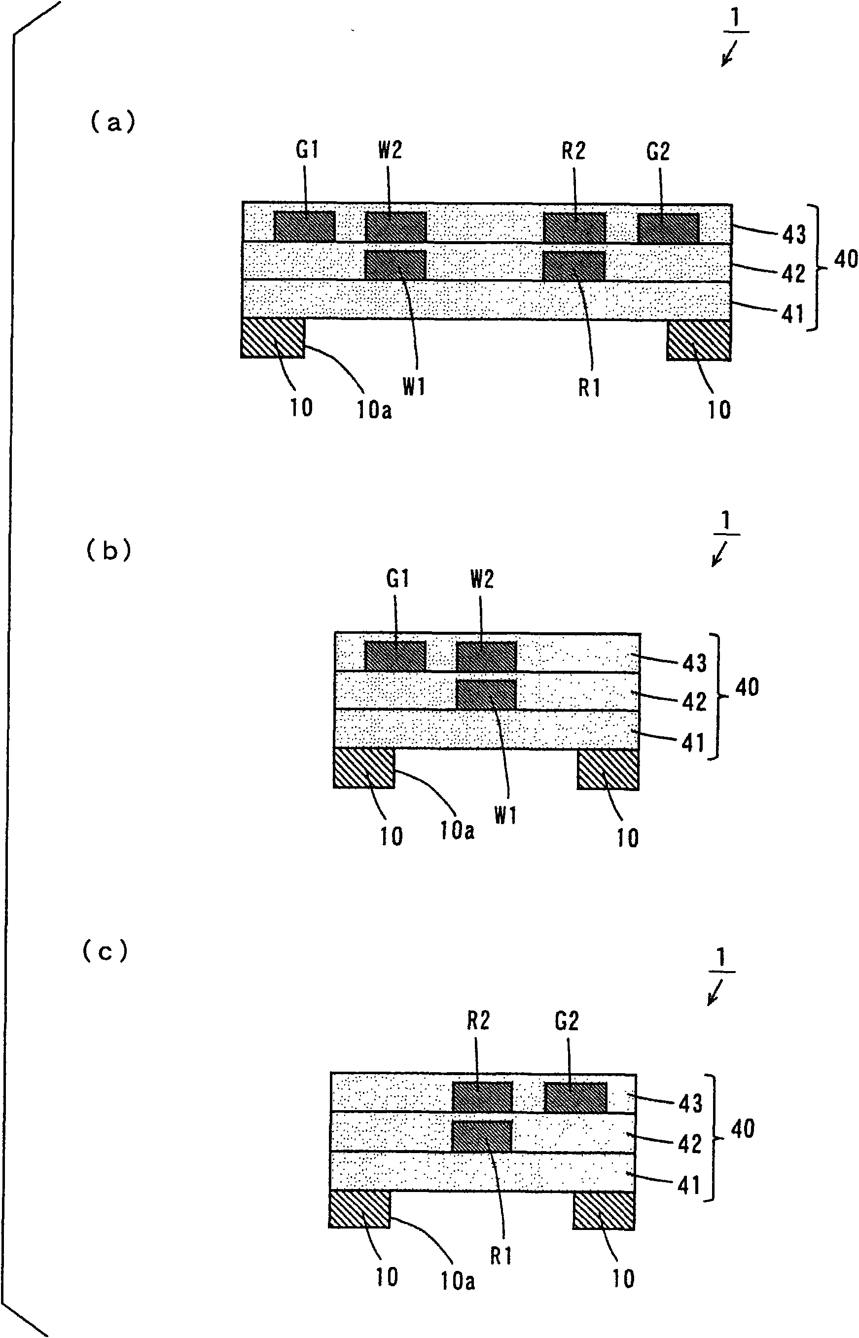
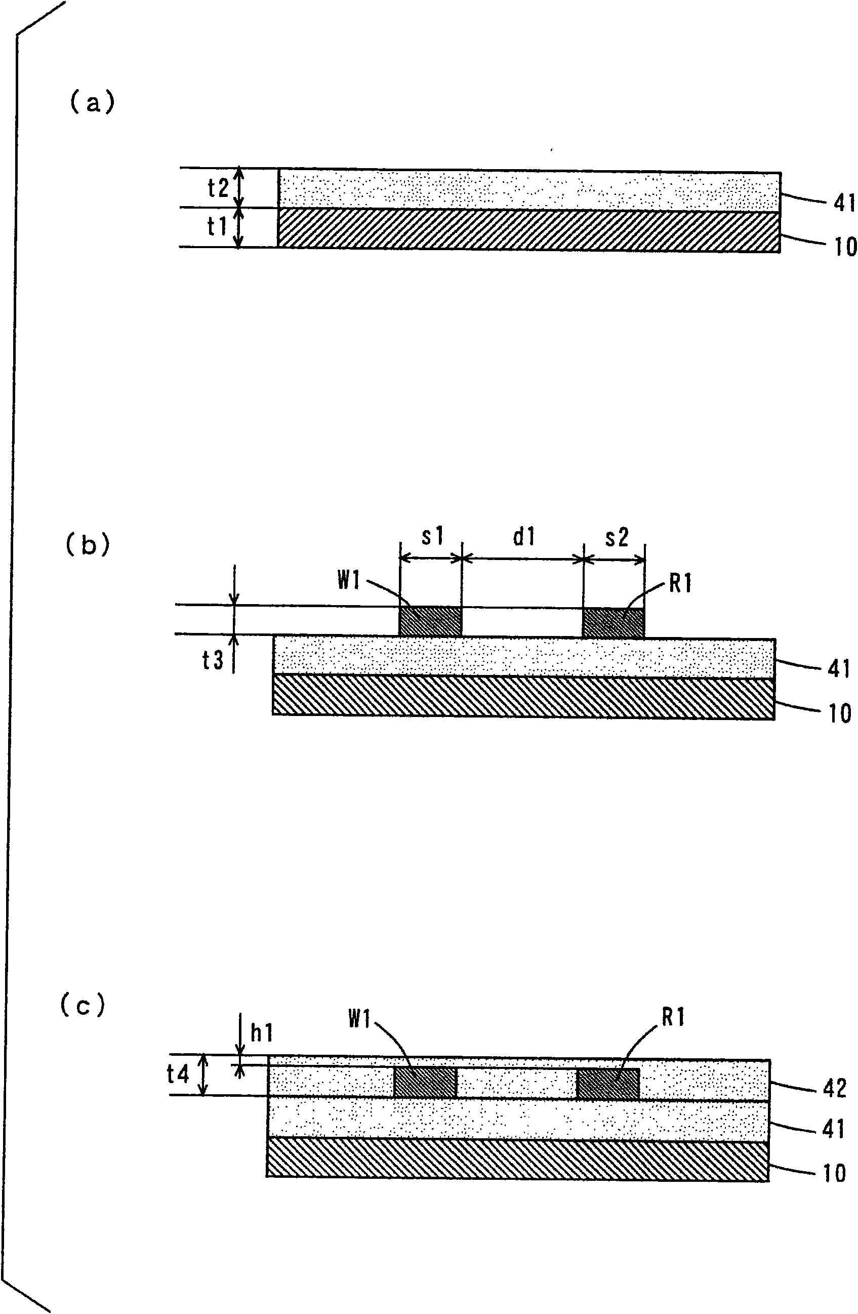
[0051] figure 1 is a plan view of the suspension board in the first embodiment of the present invention, figure 2 yes figure 1 A vertical cross-sectional view of the suspension board 1 of FIG. In addition, in figure 2 Among them, (a) means figure 1 The A-A line view cross-sectional view, (b) represents the B-B line view cross-sectional view, (c) represents the C-C line view cross-sectional view.

[0052] Such as figure 1 As shown, the suspension board 1 has a suspension main body 10 formed of a metal elongated board. As indicated by thick solid lines, the write wiring traces W1 and W2 and the read wiring traces R1 and R2 are formed on the suspension main body 10 .

[0053] At the front end of the suspension body 10 , a U-shaped opening 11 is formed to form a magnetic head mounting portion (hereinafter referred to as a tongue) 12 . The tongue portion 12 is bent at the position of the dotted line R so as to form a pr...

no. 2 approach

[0107] Figure 5 It is a longitudinal sectional view showing the suspension board in the second embodiment of the present invention. Moreover, in Figure 5 Among them, (a) means figure 1 The A-A line sectional view of , (b) represents the B-B line sectional view, and (c) represents the C-C line sectional view.

[0108] The suspension board 2 of this embodiment and figure 2 The suspension board 1 differs in the following points.

[0109] Such as Figure 5 As shown in (a), in the present embodiment, the ground pattern G3 is formed between the write wiring trace W2 and the read wiring trace R2 on the third insulating layer 43 in the cross section viewed along the line A-A.

[0110] In this case, the ground trace G3 can sufficiently prevent crosstalk from occurring between the write wiring traces W1 , W2 and the read wiring traces R1 , R2 .

[0111] In addition, if Figure 5 As shown in (b), the ground pattern G3 is formed on the other side of the write wiring pattern W2 ...


PUM

PropertyMeasurementUnit
thicknessaaaaaaaaaa
thicknessaaaaaaaaaa
thicknessaaaaaaaaaa

Abstract

The invention provides a wiring circuit base plate. A first insulating layer is formed on a suspension main body part, and a wiring pattern for writing is formed on the first insulating layer; a second insulating layer is formed on the first insulating layer in a way of covering the wiring pattern; on the second insulating layer, a wiring pattern for writing is formed above the wiring pattern for writing; in addition, on the second insulating layer, a grounding pattern is formed and has a distance with the side of the wiring pattern for writing; a third insulating layer is formed on the second insulating layer in a way of covering the wiring pattern and the grounding pattern; and an opening part is formed in the area of the suspension main body part under the wiring pattern for writing.

Description

technical field [0001] The present invention relates to a wired circuit board. Background technique [0002] Actuators are used in drive devices such as hard disk drives. This type of actuator has an arm provided rotatably about a rotation axis, and a suspension board for a magnetic head mounted on the arm. The suspension board is a wiring circuit board for positioning a magnetic head on a predetermined track of a magnetic disk. [0003] Figure 6 It is a longitudinal sectional view showing an example of a conventional suspension board. exist Figure 6 In the suspension board 900 of , an insulating layer 903 is formed on a metal substrate 902 . A pair of write conductors W1 and W2 and a pair of read conductors R1 and R2 are formed in order on the insulating layer 903 . [0004] One ends of the conductors W1, W2, R1, and R2 are respectively connected to a magnetic head (not shown). In addition, the other ends of the conductors W1, W2, R1, and R2 are electrically connecte...

Claims


Application Information

Patent Timeline
Patent Type & Authority Applications(China)
IPC IPC(8): G11B5/48
Inventor 本上满龟井胜利
Owner NITTO DENKO CORP
Why Eureka
Try Eureka