Actuating unit for a constant mesh transmission and constant mesh transmission comprising such an actuating unit

A technology for operating units and transmissions, which is applied to components with teeth, belts/chains/gears, transmission control, etc., which can solve the problems of complex control of shift forks, increased costs of structure and control costs, etc., and achieve reliable design , the effect of high flexibility

Inactive Publication Date: 2010-12-08
MAGNA POWERTRAIN AG & CO KG
View PDF8 Cites 2 Cited by
  • Summary
  • Abstract
  • Description
  • Claims
  • Application Information

AI Technical Summary

Problems solved by technology

[0003] Since a maximum of one transmission gear must be engaged at any one time, the control of the shift fork of the moving claw ring is rather complex, and the associated enormous structural and control outlays lead to a corresponding increase in costs.

Method used


Image

  • Actuating unit for a constant mesh transmission and constant mesh transmission comprising such an actuating unit
  • Actuating unit for a constant mesh transmission and constant mesh transmission comprising such an actuating unit
  • Actuating unit for a constant mesh transmission and constant mesh transmission comprising such an actuating unit

Examples


Embodiment Construction

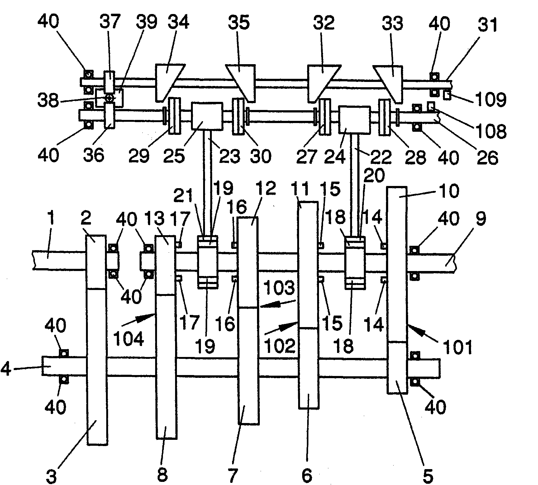
[0052] figure 1 Designates a part of the claw clutch which is provided with the actuating unit designed according to the invention and otherwise designed in a known manner.

[0053] The input shaft 1 is connected via an input gear 2 to a transmission gear 3 , which is connected rotatably and axially immovably to a transmission shaft 4 . On the transmission shaft 4, other transmission gears 5, 6, 7, 8 are fixed in a non-rotational and axially immovable manner, and they are respectively connected with the shifting gear 10, 11, 12, 13 are meshed and together form gear sets 101, 102, 103, 104 for forming the first, third, fifth and sixth gears.

[0054] On the inner sides of the shifting gears 10, 11, 12, 13, claw-toothed appendages 14, 15, 16, 17 are respectively arranged, which are designed to be inserted into bores 18, 19 which extend parallel to the output shaft 9 through Claw rings 20 , 21 mounted on the output shaft in a rotationally fixed but axially displaceable manner. ...


PUM


Abstract

The invention relates to an actuating unit for a constant mesh transmission, particularly of a motor vehicle, comprising a selector fork that can be axially displaced at least between a first position associated with a first gear step of the constant mesh transmission and a neutral position. A positioning shaft is provided, on which two positioning elements for the selector fork are supported axially displaceably, but non-rotatably. The positioning elements comprise each a contact section for the temporary contact with the selector fork. The positioning shaft can be rotated together with the positioning elements for setting predetermined different angular positions of the positioning elements. Each positioning element is associated with an actuating element, by which the positioning element can be displaced as a function of the set angular position thereof axially along the positioning shaft. Furthermore, the invention relates to a constant mesh transmission comprising such an actuating device.

Description

technical field [0001] The invention relates to an operating unit of a claw transmission, in particular of a motor vehicle, having a shift fork which can be pivoted at least between a first position corresponding to the first transmission gear of the claw transmission and a neutral position. to move. Furthermore, the invention relates to a claw transmission comprising an actuating unit of this type. Background technique [0002] The claw transmission operating unit is not only used in automatic transmissions, but also in manual transmissions. In particular, they are also increasingly used in load transmissions, such as dual clutch transmissions or automated manual transmissions. In these transmissions, each shift fork is assigned a claw ring (shift engagement sleeve) which is displaceably but non-rotatably mounted on the transmission shaft and which is displaceable by the selector fork. The claw ring is always placed between shift gears (live gears) that are rotatably but...

Claims


Application Information

Patent Timeline
Patent Type & Authority Applications(China)
IPC IPC(8): F16H63/30
CPCF16H2061/2838F16H61/32F16H2063/3056F16H61/28F16H63/304F16H2061/2869
Inventor 沃尔弗拉姆·哈斯温德
Owner MAGNA POWERTRAIN AG & CO KG
Why Eureka
Try Eureka