Bone nail for the heel

A bone nail and heel technology, applied in tibial-calcaneal arthrodesis, in the field of osteosynthesis kits, can solve the problems of small curvature radius and inability to consider the heel area

Inactive Publication Date: 2010-12-15
帕拉贡28公司
View PDF0 Cites 1 Cited by
  • Summary
  • Abstract
  • Description
  • Claims
  • Application Information

AI Technical Summary

Problems solved by technology

[0003] In addition, partially curved tibial nails are known, but the radius of curvature of said known nails is relatively

Method used


Image

  • Bone nail for the heel
  • Bone nail for the heel
  • Bone nail for the heel

Examples


Embodiment Construction

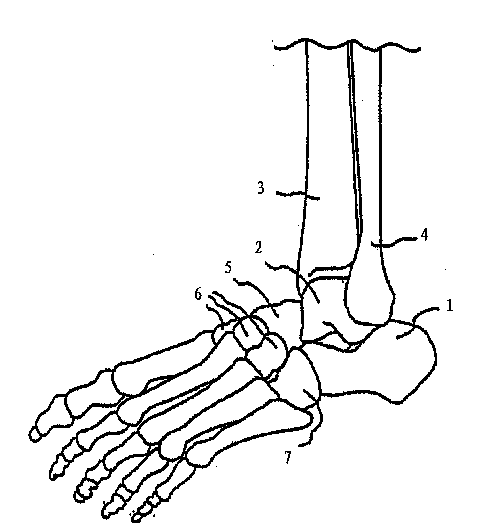
[0051] figure 1 The lower leg is shown in a position rotated approximately 45° medially. The figure shows the bone which is important for the application of the bone screw according to the invention. This is primarily the calcaneus 1, the talus 2 and the tibia 3. The fibula 4, navicular 5, cuneiform 6 and cuboid 7, also shown, are drawn for completeness purposes only.

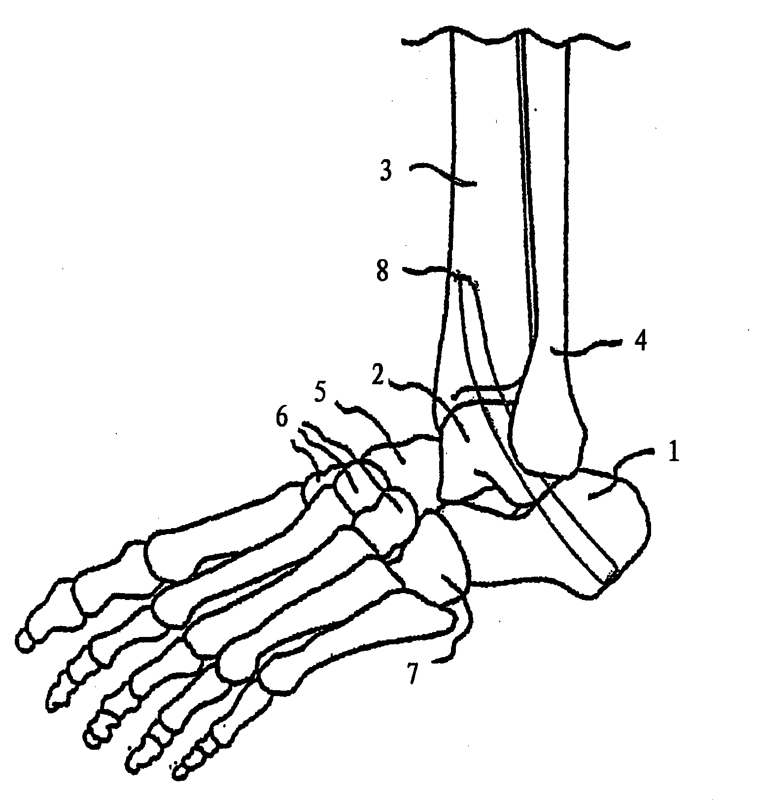
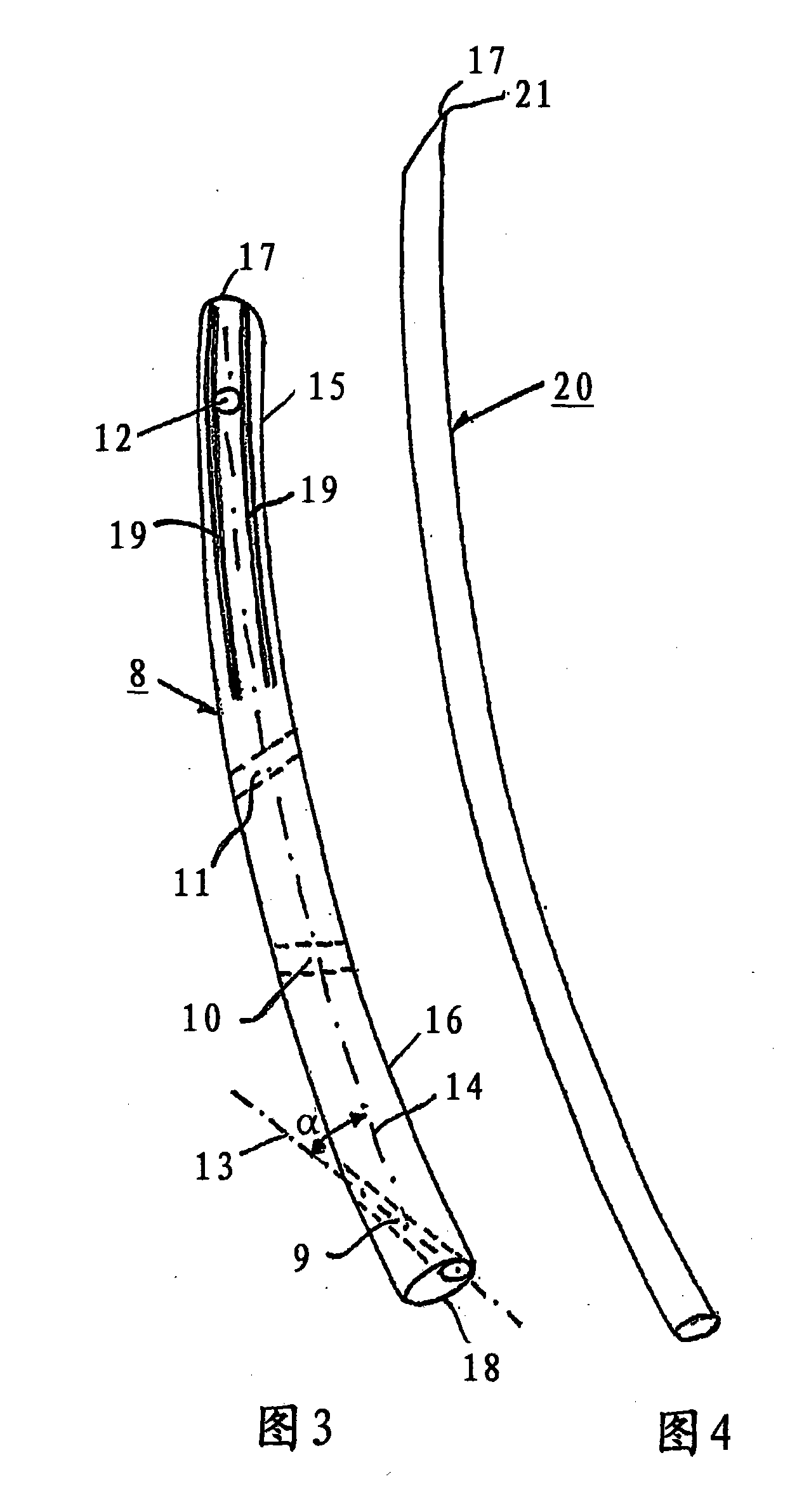
[0052] exist figure 2 The bone screw according to the invention, which is formed as an implant 8 , is shown in the middle, which is implanted through the calcaneus 1 and the talus 2 to the lower part of the tibia 3 . Such as image 3 As shown, the implant 8 is continuously curved in a plane with a radius of curvature R of typically 190 mm. The bend is over the entire length L of the implant 8 I Extended above, this length is typically 140mm. its diameter D 1 Usually 11mm. Length L of implant 8 I and diameter D 1 The ratio between L I / D 1 Usually 12.7.

[0053] The implant 8 comprises a plurality...


PUM

PropertyMeasurementUnit
Diameteraaaaaaaaaa

Abstract

The bone nail is intended for the heel. It comprises a front part (15) that is intended to be inserted in the bone and is provided with a tip (17) and it also comprises a rear part (16) having an end (18). The rear part (16) is rigid at a length of at least 120 mm, starting from the end (18). The bone nail is curved in a plane and the curvature for each infinitesimal section of the bone nail has a curvature radius that is at least 130 mm. The key advantages that can be achieved with the bone nail according to the invention and thanks to the surgical technique that becomes possible with it are the possibility to adjust the heel with high precision relative to the lower leg and knee axis, the avoidance of the risk of an injury to the plantar nerves, and a less invasive implant compared to known surgical techniques using other nails.

Description

technical field [0001] The present invention relates to a bone screw for the heel according to the preamble of claim 1, an osteosynthesis kit according to the preamble of claim 16, and a bone screw in the tibia according to claim 17. - Application in calcaneal (ankle) arthrodesis. Background technique [0002] Bending intramedullary nails in partial regions have long been known. As an example, so-called ENDER nails can be mentioned here. However, these known nails are designed elastically and flexibly for their intended use, so that they already bend when subjected to small loads. Due to the flexibility of said known nails, it does not matter that the middle part is straight and has no bends. Said known ENDER nails are also distinguished by their relative length and slenderness. In the case of ENDER, the ratio between the diameter of the nail and the length of the nail is in the range of 1:60 to 1:110. Its use in the heel area is ruled out for this reason. [0003] Par...

Claims


Application Information

Patent Timeline
IPC IPC(8): A61B17/17A61B17/68A61B17/16A61B17/72
CPCA61B2017/1775A61B17/1717A61B17/7283A61B17/72A61B17/7291A61B17/7233A61B17/7208A61B17/1775
Inventor K·克劳
Owner 帕拉贡28公司
Why Eureka
Try Eureka