Test chamber with temperature and humidity control

A test box and controller technology, applied in refrigerators, refrigeration components, household appliances, etc., can solve the problem of weakening the overall utility of the equipment

Inactive Publication Date: 2010-12-15
文彻达因有限公司
View PDF0 Cites 7 Cited by
  • Summary
  • Abstract
  • Description
  • Claims
  • Application Information

AI Technical Summary

Problems solved by technology

The existing system either limits the temperature / humidity range, or limits the amount of allowable heat dissipation due to dynamic loads, or the existing system is proprietary such that the overall utility of the equipment is compromised

Method used


Image

  • Test chamber with temperature and humidity control
  • Test chamber with temperature and humidity control
  • Test chamber with temperature and humidity control

Examples


Embodiment Construction

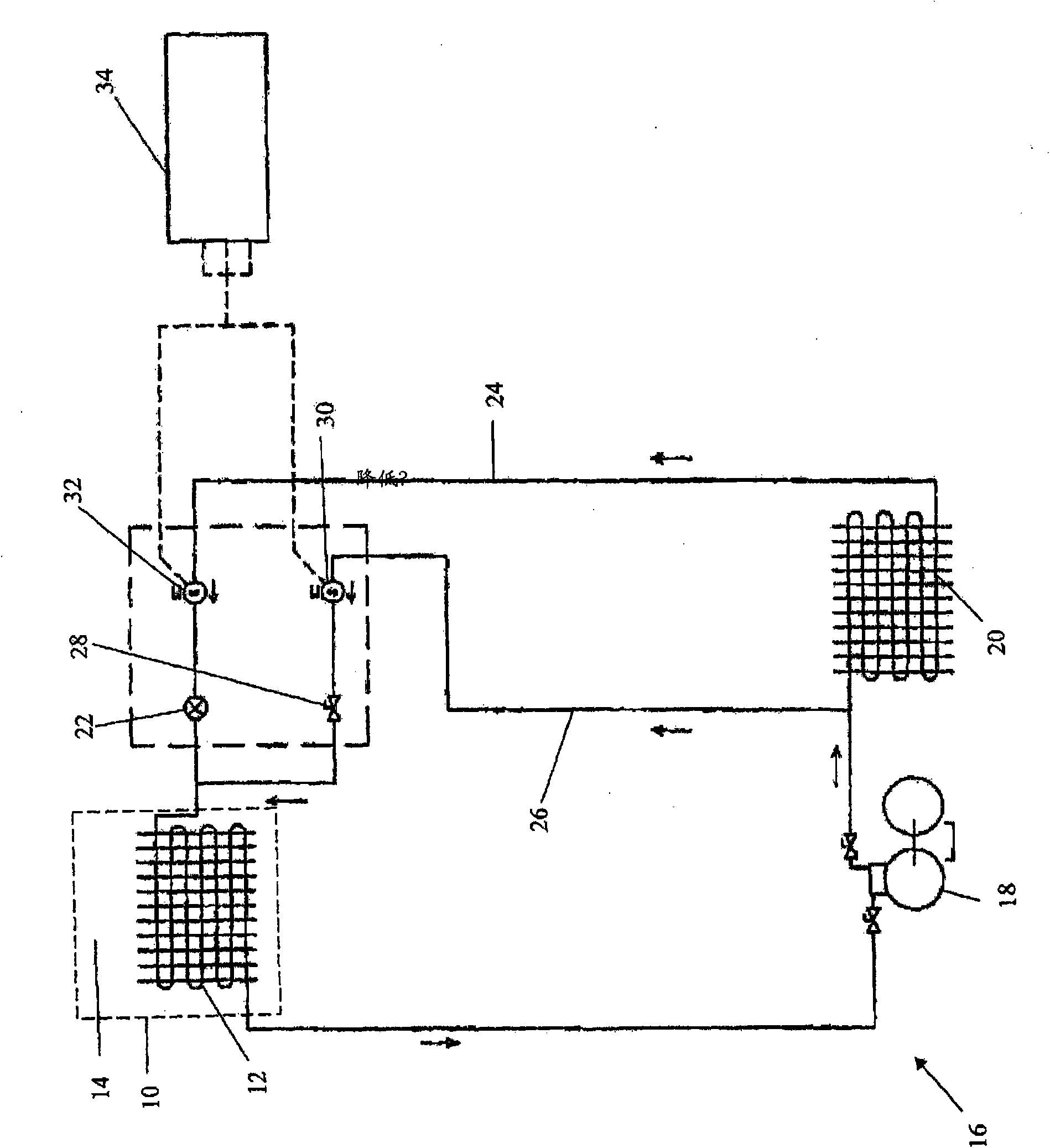
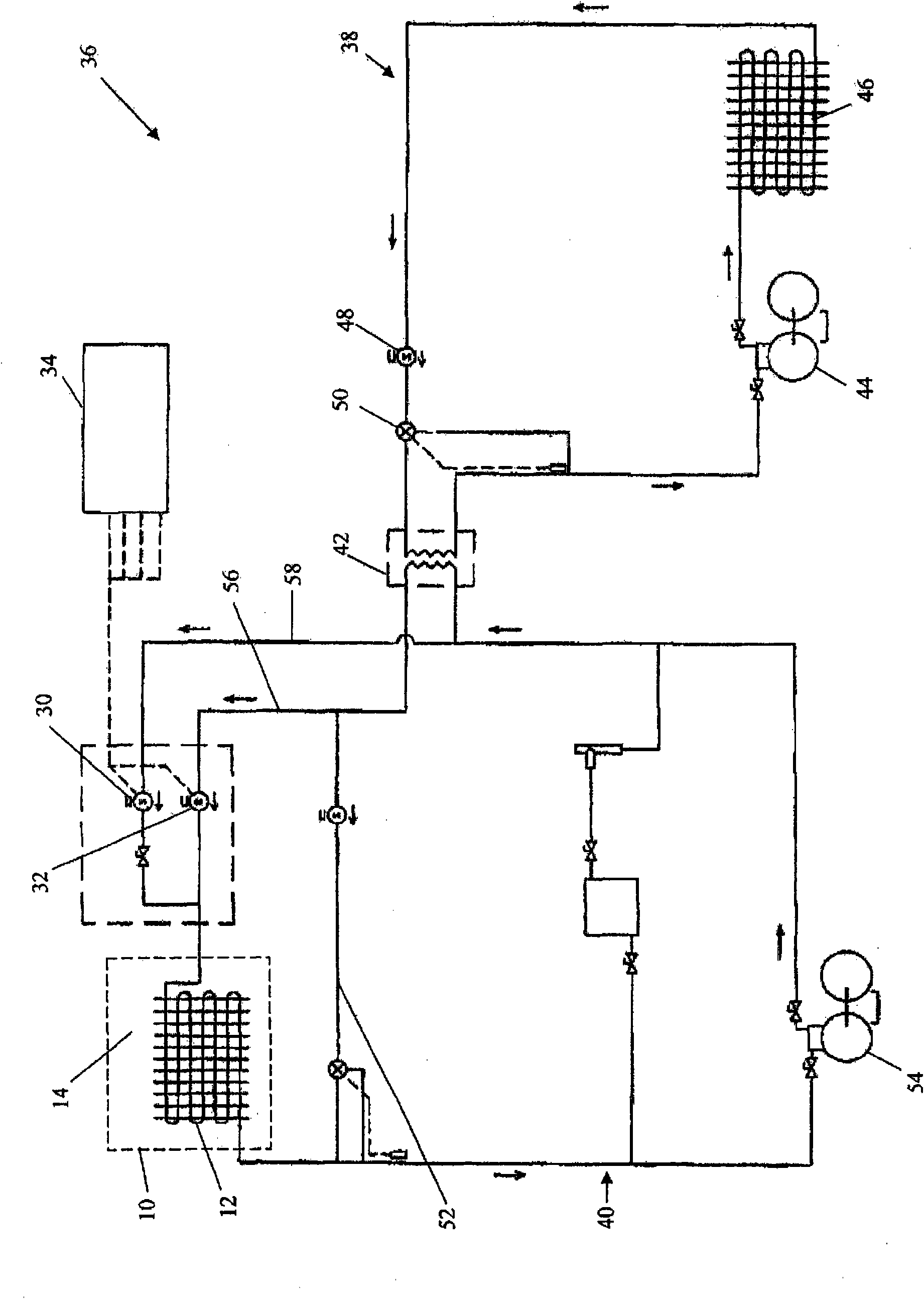
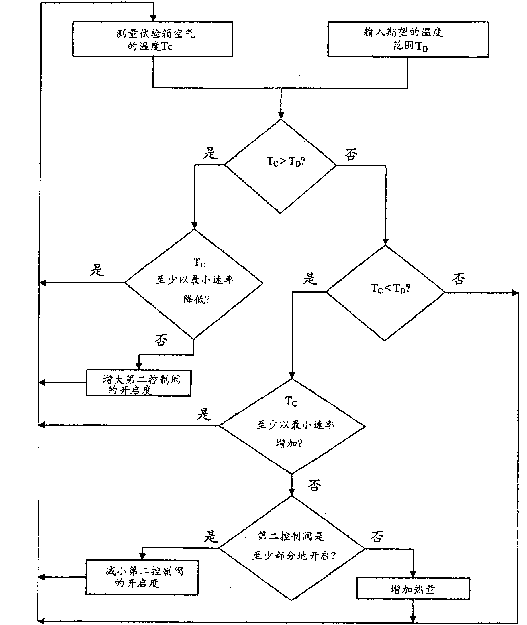
[0011] Before describing any embodiment of the invention in detail, it is to be understood that the invention is not limited to the details of construction and the arrangement of parts set forth in the following description of this application or shown in the following drawings. The invention is capable of other embodiments and of being practiced or carried out in various ways. Also, it is to be understood that the phraseology and phraseology used herein are for the purpose of description and should not be regarded as limiting. As used herein, "comprises," "comprising," or "having" and variations thereof is meant to encompass the items listed thereafter and equivalents thereof as well as additional items. Unless specified or otherwise limited, the terms "mount," "connect," "support," and "couple" and variations thereof are used broadly and encompass both direct and indirect mounting, connecting, supporting, and coupling. Furthermore, "connected" and "coupled" are not limited ...


PUM


Abstract

A test chamber that is capable of operating in a mode where the temperature of the chamber is efficiently cooled without removing a substantial amount of moisture from the air. The test chamber includes a structure defining a work space having air, and a temperature control system. The temperature control system includes a heat exchanger positioned to communicate with the air in the work space, a source of cold fluid coupled to the heat exchanger, a source of hot fluid coupled to the heat exchanger, and a controller for controlling a mixture of cold fluid and hot fluid entering the heat exchanger The controller is programmed such that the temperature of the mixture entering the heat exchanger is controlled to limit a temperature differential between the heat exchanger and the air in the work space.

Description

【Technical field】 [0001] The invention relates to a temperature and humidity control test chamber and a method for controlling the temperature and humidity therein. 【Background technique】 [0002] General purpose environmental chambers are typically designed for several tasks requiring different modes of operation. One such task may be high and low temperature switching and stabilization in the temperature range from 180°C to -70°C. Typically, to achieve lower temperatures with mechanical refrigeration, a cascade refrigeration system is used. This requires two separate refrigeration circuits (stages): a high-pressure refrigerant in the lower stage and a relatively low-pressure refrigerant in the upper stage to "cascade" the heat from the chamber, reducing the air temperature in the enclosure. [0003] Another task may be to precisely control the temperature and humidity within the cabinet workspace. When operating in temperature / humidity mode, it is important to maintain ...

Claims


Application Information

Patent Timeline
IPC IPC(8): G01N17/00
CPCF25B41/04F25B2400/0403F25B2600/2501F24F3/1405F25D21/04F25B47/006F25B41/20
Inventor D·E·伊明克C·A·彼得森A·R·维尔德特
Owner 文彻达因有限公司
Why Eureka
Try Eureka