
Method for machining normal straight profile cylindrical worm by using horizontal lathe

A horizontal lathe and worm technology, applied in the direction of worms, toothed components, belts/chains/gears, etc., can solve the problem that the normal straight profile cylindrical worm cannot be processed, shorten the production cycle and improve the ability , The effect of reducing manufacturing costs

Active Publication Date: 2010-12-22
HARBIN TURBINE +1
View PDF5 Cites 5 Cited by
  • Summary
  • Abstract
  • Description
  • Claims
  • Application Information

AI Technical Summary

Problems solved by technology

[0003] The purpose of the present invention is to solve the problem that the normal straight-profile cylindrical worm cannot be processed on a horizontal lathe, and to provide a method for processing the normal straight-profile cylindrical worm by using a horizontal lathe

Method used


Image

  • Method for machining normal straight profile cylindrical worm by using horizontal lathe
  • Method for machining normal straight profile cylindrical worm by using horizontal lathe
  • Method for machining normal straight profile cylindrical worm by using horizontal lathe

Examples


specific Embodiment approach 1

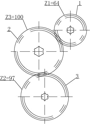
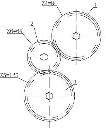
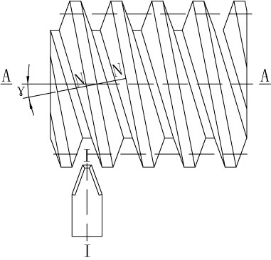
[0010] Specific implementation mode one: combine Figure 1 to Figure 10 Describe this implementation mode, this implementation mode is realized through the following steps:

[0011] Step 1. Change the number of teeth of the gear set in the wheel box of the horizontal lathe to change the pitch: the axial pitch of the horizontal lathe is not equal to the axial pitch of the normal straight-profile cylindrical worm. In order to make the axial pitch of the horizontal lathe It is equal to the axial pitch of the normal straight-profile cylindrical worm. First, the number of teeth of the gear set in the hanging wheel box of the horizontal lathe should be changed to change the transmission ratio i of the hanging wheel box. There are three straight teeth in the hanging wheel box of the horizontal lathe Cylindrical gears are driving wheel 1, driven wheel 2 and intermediate wheel 3. Before the change, the parameters of each gear are: the number of teeth of the driving wheel 1 is Z1, the n...

specific Embodiment approach 2

[0014] Specific implementation mode two: combination figure 1 and figure 2 To describe this embodiment, the rotating knife rod 4 in step 2 of this embodiment is provided with a rotation scale 4-1. Make the cutter head reach the accurate metering scale value when rotating. Other steps are the same as in the first embodiment.

[0015] Application example of the present invention: C620 horizontal lathe is now used to process normal straight profile cylindrical worm, C620 lathe axial pitch P1=9.42, modulus m=3, the parameters of the gear set in the hanging wheel box are shown in Table 1:

[0016] Table 1:

[0017]

Drive wheel Z1

Driven wheel Z2

Intermediate wheel Z3

Modulus m

1.75

1.75

1.75

Number of teeth Z

64

97

100

pressure angle α

20°

20°

20°

Bore spline

φ28+0.02×φ23×6

φ28+0.02×φ23×6

φ38+0.02×φ33×6

Gear width

40-0.2

40-0.2

40-0.2

[0018] The axial pitch of the...


PUM


Abstract

The invention provides a method for machining a normal straight profile cylindrical worm by using a horizontal lathe, relating to the method of machining the normal straight profile cylindrical worm. The invention aims to solve the problem that the normal straight profile cylindrical worm can not be machined on the horizontal lathe. The method comprises the following steps: 1, changing the toothnumber of a gear set in the change gear box of the horizontal lathe to achieve the change of screw pitches; 2, adopting a rotating cutter bar (4) to machine the normal straight profile cylindrical worm; and 3, firstly enabling a plane of a blade to be parallel to a normal plane of a spiral line, then leading the plane of the blade to rotate around the own axial center (I-I) of the cuter bar by a lead angle (gamma), and at the same time, ensuring the front blade to be in parallel with an oblique line (N-N), thereby ensuring that a tooth shape on a normal profile of a worm is trapezoid. The method is used for machining the normal straight profile cylindrical worm.

Description

technical field [0001] The invention relates to a method for a normal straight profile cylindrical worm. Background technique [0002] The normal straight profile cylindrical worm is also called the extended involute worm. The tooth profile on the axial section is a convex curve, and has a straight tooth profile on the normal section. It is often used as a multi-head precision worm for machine tools, and the efficiency can reach 0.9. Ordinary horizontal lathes generally process Archimedes cylindrical worms, which have straight tooth profiles on the axial section and convex curves on the normal section (see Figure three ) This kind of worm is easy to process and widely used, but it is difficult to process when the lead angle is large, so it is generally used for transmission with a small number of heads, small load, low speed or less important; when processing Archimedes cylindrical worm, its The modulus is standard and should be the axial modulus (end modulus) of the worm, ...

Claims


Application Information

Patent Timeline
IPC IPC(8): B23F13/02
Inventor 隋朝龙崔会彬韩志双宣利红成国富范立刚魏成双付贵言
Owner HARBIN TURBINE
Learn More