Method for compensating vibration of automatic and ultrasonic steel pipe flaw detection probe

A technology of ultrasonic flaw detection and vibration compensation, applied in the direction of using ultrasonic/sonic/infrasonic, material analysis using sonic/ultrasonic/infrasonic, and measuring devices, which can solve the problems of reliability deterioration and limited effect.

Inactive Publication Date: 2010-12-22
INST OF METAL RESEARCH - CHINESE ACAD OF SCI
View PDF1 Cites 14 Cited by
  • Summary
  • Abstract
  • Description
  • Claims
  • Application Information

AI Technical Summary

Problems solved by technology

For the problem of the deterioration of the reliability of defect detection caused by probe vibration, the usual method is to increase the damping of pr

Method used


Image

  • Method for compensating vibration of automatic and ultrasonic steel pipe flaw detection probe
  • Method for compensating vibration of automatic and ultrasonic steel pipe flaw detection probe
  • Method for compensating vibration of automatic and ultrasonic steel pipe flaw detection probe

Examples


Embodiment 1

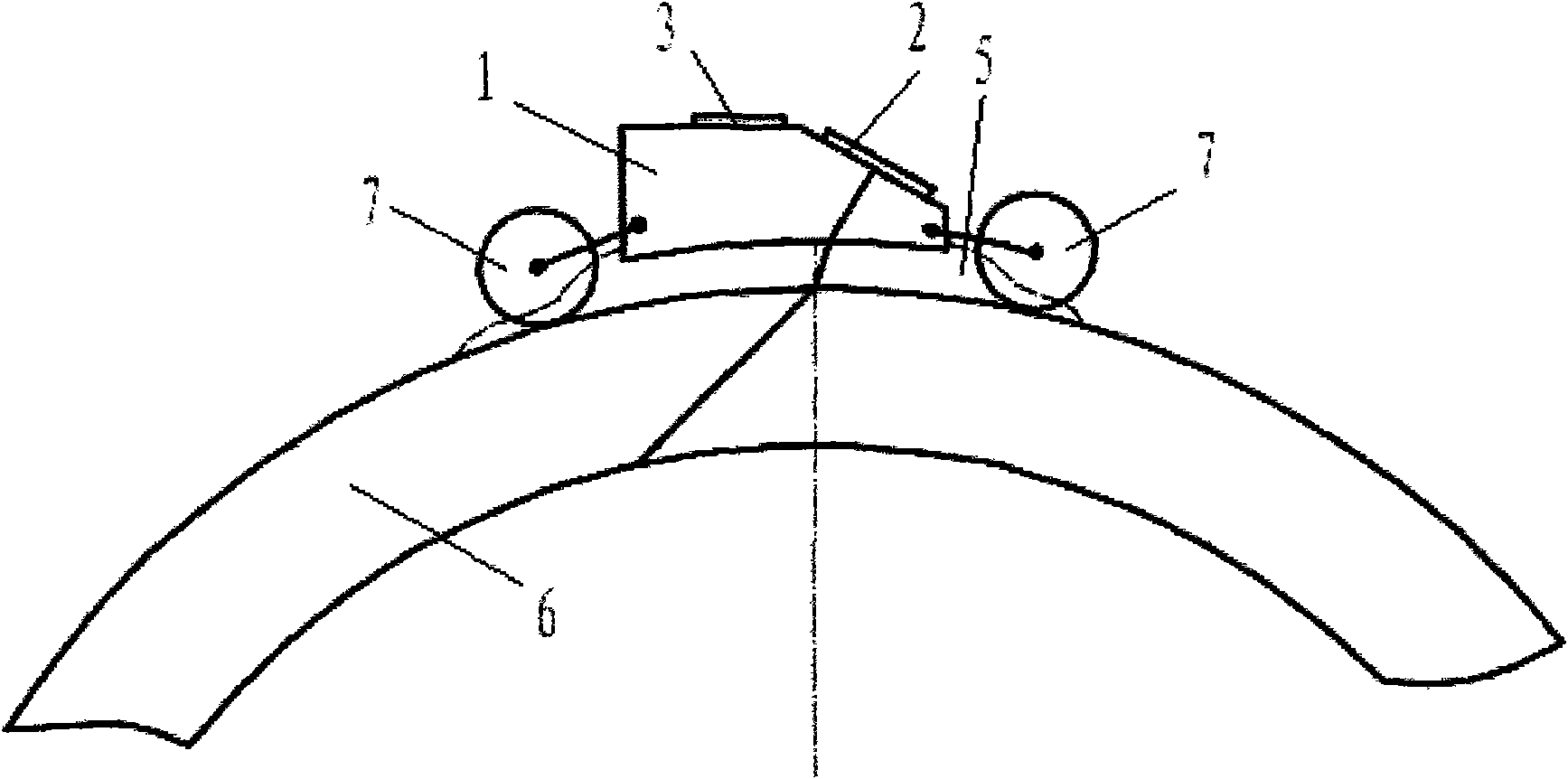
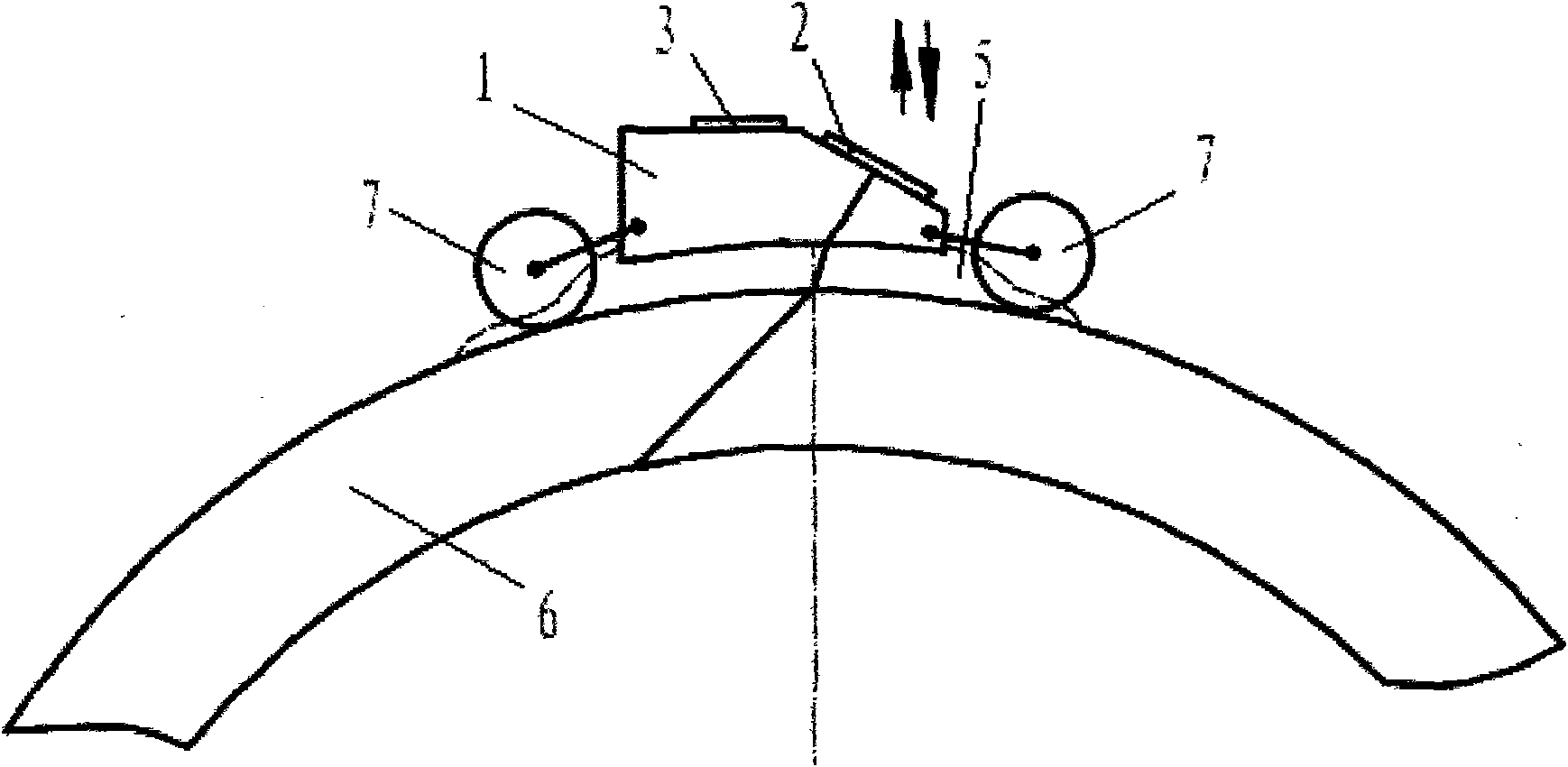
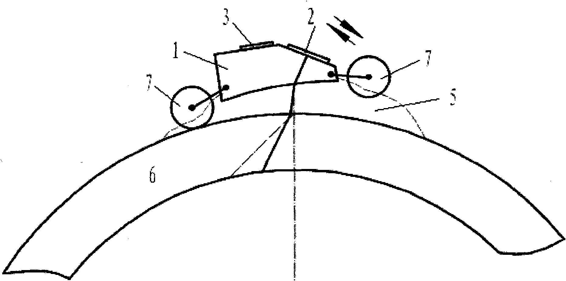
[0035] A steel pipe automatic ultrasonic flaw detection probe vibration compensation method based on the water film coupling steel pipe nondestructive flaw detection technology, which automatically monitors the change of the coupling water film thickness, and adjusts the alarm signal gate value of the steel pipe automatic ultrasonic flaw detection based on this to realize the defect detection of the steel pipe detection.

[0036] The vibration compensation method of the steel pipe automatic ultrasonic flaw detection probe is based on the following basic principles: the upper and lower vibrations of the probe cause the change of the thickness of the coupled water film, which causes the diffusion of the sound beam to cause the change of the defect signal amplitude, and the warping of the probe causes the change of the thickness of the coupled water film and the acoustic The change of the beam incident angle leads to the change of the defect signal amplitude; the defect signal amp...

Embodiment 2

[0051] The content of this embodiment is basically the same as that of Embodiment 1, and its difference mainly lies in:

[0052] When the coupling water film 5 has a certain thickness and can separate e1 and e2 echoes, suppose the sound path time difference between e1 and e2 echoes is t1, and the sound velocity in water is v1, then the thickness of the coupling water film 5 is d1=t1*v1 / 2. If the vibration of the probe causes the thickness of the coupling water film 5 to change, then Δt1 and Δd1 can be calculated respectively. Adjust the left and right positions of the W2 and W3 gates according to Δt1, that is, gate tracking, check the relationship curve of the defect signal with the thickness of the coupling water film 5 according to Δd1, and automatically adjust the height of the gates W2 and W3.

Embodiment 3

[0054] The content of this embodiment is basically the same as that of Embodiment 1, and its difference mainly lies in:

[0055] When the coupling water film 5 has a certain thickness but cannot separate e1 and e2 echoes, let the sound path time difference between e1 and B1 echoes be t1, the sound path time difference between B1 and B2 echoes be t2, and the sound velocity in water be v1, The sound velocity of the longitudinal wave in the steel is v2, then the steel pipe wall thickness d2=t2*v2 / 2 of the tested steel pipe 6, then the thickness of the coupled water film 5 is d1=(t1-t2)*v1 / 2. If the vibration of the probe causes the thickness of the coupling water film 5 to change, then Δ(t1-t2) and Δd1 can be calculated respectively. According to Δ(t1-t2), the left and right positions of W2 and W3 gates are correspondingly adjusted, that is, the gates are tracked. According to Δd1, the relationship curve of defect signal with the change of water film thickness is checked and the ...


PUM

PropertyMeasurementUnit
Wall thicknessaaaaaaaaaa
Outer diameteraaaaaaaaaa

Abstract

The invention relates to a method for compensating the vibration of an automatic and ultrasonic steel pipe flaw detection probe, which is based on water film coupled steel pipe non-destructive flaw detection technology. The method is characterized in that: an alarm signal gate value of automatic and ultrasonic steel pipe flaw detection is adjusted by automatically monitoring the thickness change of a coupled water film so as to realize flaw detection of a steel pipe. In order to solve the problem that upward and downward vibration of the probe affect the flaw detection, the invention discloses compensation technology which can dynamically compensate the adverse effect of the thickness change of the water film which is caused by probe vibration on the flaw detection in real time without increasing expense on instrument hardware of a detection passage. A flaw signal of the probe vibration during the automatic and ultrasonic steel pipe flaw detection is compensated automatically in real time and the omission of the flaw detection is avoided. A technical problem which cannot be solved for a long time is solved.

Description

technical field [0001] The invention relates to automatic ultrasonic flaw detection technology for steel pipes, and in particular provides a vibration compensation method for automatic ultrasonic flaw detection probes for steel pipes. Background technique [0002] Steel pipe is an important structural material widely used. It has been pointed out in the Chinese patent application document with application number 200810011490.X that in the production process of steel pipe, due to various accidents, there are often longitudinal cracks and transverse cracks on the steel pipe wall. Defects such as cracks, folds, delamination, etc. If the steel pipe is defective, it will break during use and cause an accident, or even cause serious consequences, which may cause major economic losses or even casualties. Therefore, all manufacturers of steel pipes in the world need to have perfect non-destructive testing equipment for online flaw detection of steel pipes. . [0003] For steel pip...

Claims


Application Information

Patent Timeline
IPC IPC(8): G01N29/24G01N29/30G01B17/02
Inventor 蔡桂喜韩晓华于冰孟令华黄绪萍李庆卓
Owner INST OF METAL RESEARCH - CHINESE ACAD OF SCI
Why Eureka
Try Eureka