Spherical three-degree-of-freedom parallel mechanism antenna structure system

A technology of antenna structure and degrees of freedom, applied in directions such as antennas, antenna supports/installation devices, electrical components, etc., can solve problems such as continuous tracking of satellites, and achieve the effect of saving production costs

Active Publication Date: 2010-12-22
SHANGHAI UNIV +1
View PDF2 Cites 35 Cited by
  • Summary
  • Abstract
  • Description
  • Claims
  • Application Information

AI Technical Summary

Problems solved by technology

[0004] The traditional classic remote sensing and telemetry low-orbit satellite antenna design generally adopts the elevation-azimuth (EL-AZ type) antenna seat, which has an overhead "blind cone area", a...

Method used


Image

  • Spherical three-degree-of-freedom parallel mechanism antenna structure system
  • Spherical three-degree-of-freedom parallel mechanism antenna structure system
  • Spherical three-degree-of-freedom parallel mechanism antenna structure system

Examples


Embodiment 1

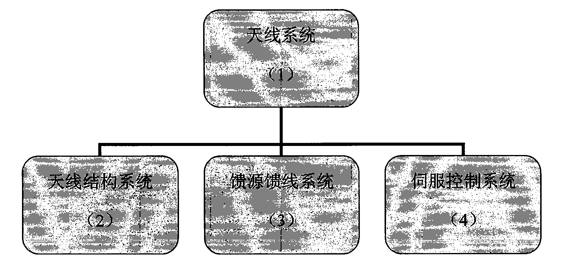
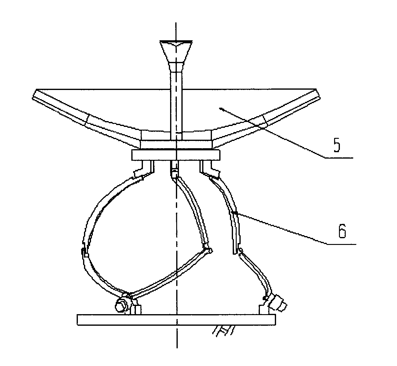
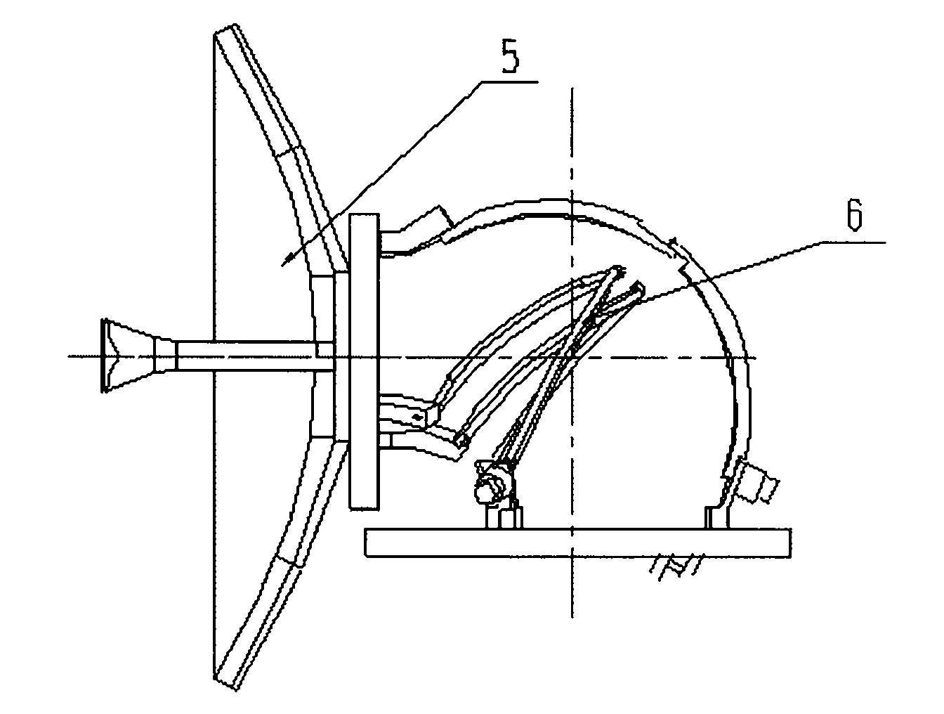
[0022] see figure 1 , figure 2 with image 3 , this spherical three-degree-of-freedom parallel mechanism antenna structure system is composed of an antenna reflector 5 and an antenna base 6. The structure of the antenna base 6 is: it consists of upper and lower platforms 11, 16, through the same structure It is composed of three branch mechanisms. exist figure 1 It shows that the antenna system 1 is composed of the antenna structure system 2, the corresponding feed source system 3, the servo control system 4 and its corresponding supporting electronic equipment, which realizes automatic tracking of satellites and aircraft, and completes the transmission and analysis of satellite or aircraft signals and data and processing.

[0023] see figure 2 with image 3 , the spherical three-degree-of-freedom parallel mechanism antenna structure system is composed of an antenna reflector 5 and an antenna mount 6 .

Embodiment 2

[0024] Embodiment 2: This embodiment is basically the same as Embodiment 1, and the special features are as follows: see Image 6 with Figure 7 , each said branch mechanism contains an upper garden arc support 12 and a lower garden arc support 13, between said upper platform 11 and said upper garden arc support 12, said upper garden arc Between the arc-shaped support 12 and the said lower garden arc-shaped support 13, and between the said lower garden arc-shaped support 13 and the said lower platform 16, they are respectively connected by three rotating pair hinges, and a motor 14 is directly connected or passed through a The transmission 15 connects the rotary shaft of any one of the three rotary pairs. The rotation axes of the nine revolving pairs of the three branch mechanisms all meet at the same center of the sphere. Described upper and lower two platforms 11,16 are respectively connected with upper and lower garden arc supports 12,13 and the center points of rotations...


PUM


Abstract

The invention relates to a spherical three-degree-of-freedom parallel mechanism antenna structure system, which is formed by connecting an antenna reflector and an antenna base frame. The antenna base frame is formed by connecting an upper platform and a lower platform through three branch mechanisms with the same structure; each branch is formed by connecting an upper platform, an upper circulararc-shaped bracket, a lower circular arc-shaped bracket and a lower platform through three rotating pairs, wherein one rotating pair is connected with a motor; the upper platform is fixedly connected with the antenna reflector; the lower platform is connected with a foundation frame or an antenna carrier frame; and the motor drives the lower circular arc-shaped bracket, the upper circular arc-shaped bracket, the upper platform and the antenna reflector to rotate spherically with three degrees of freedom directly or by a transmission. The spherical three-degrees-of-freedom parallel mechanism antenna structure system can perfectly acquire remote sensing and remote detecting signals and data of satellites, carrier rockets and other aircrafts, and continuously track in overhead airspace of the antenna so as to reach hemispherical working airspace and over-semisphere working airspace.

Description

technical field [0001] The invention relates to an antenna structure system based on a spherical three-degree-of-freedom parallel mechanism. Antenna structure system for aerospace remote sensing, satellite "three remote" technology (remote sensing, telemetry, remote control technology) and satellite communication. Background technique [0002] The reflector part of the antenna generally consists of a main reflector panel, a back frame structure, a center body, a balance weight structure, a sub-reflector, a focusing device and its support structure or a feedforward support structure; the antenna mount part generally has an antenna base support structure , drive shafting and transmission device, feeder and cable winding device, data detection transmission device and safety protection device. [0003] At present, the world-known aerospace remote sensing and satellite "three remote" technologies (remote sensing, telemetry, and remote control technology) adopt the classic elevat...

Claims


Application Information

Patent Timeline
IPC IPC(8): H01Q1/12H01Q3/02H01Q19/18
Inventor 沈龙龚振邦刘亮杨明德罗胜李宇
Owner SHANGHAI UNIV
Why Eureka
Try Eureka