
Illumination system

A lighting system and lighting module technology, applied in the field of lighting systems, can solve problems such as damage to the lighting module 120, ineffective heat transfer, etc., and achieve the effect of reducing the degree of life loss

Inactive Publication Date: 2010-12-29
YOUNG GREEN ENERGY
View PDF0 Cites 0 Cited by
  • Summary
  • Abstract
  • Description
  • Claims
  • Application Information

AI Technical Summary

Problems solved by technology

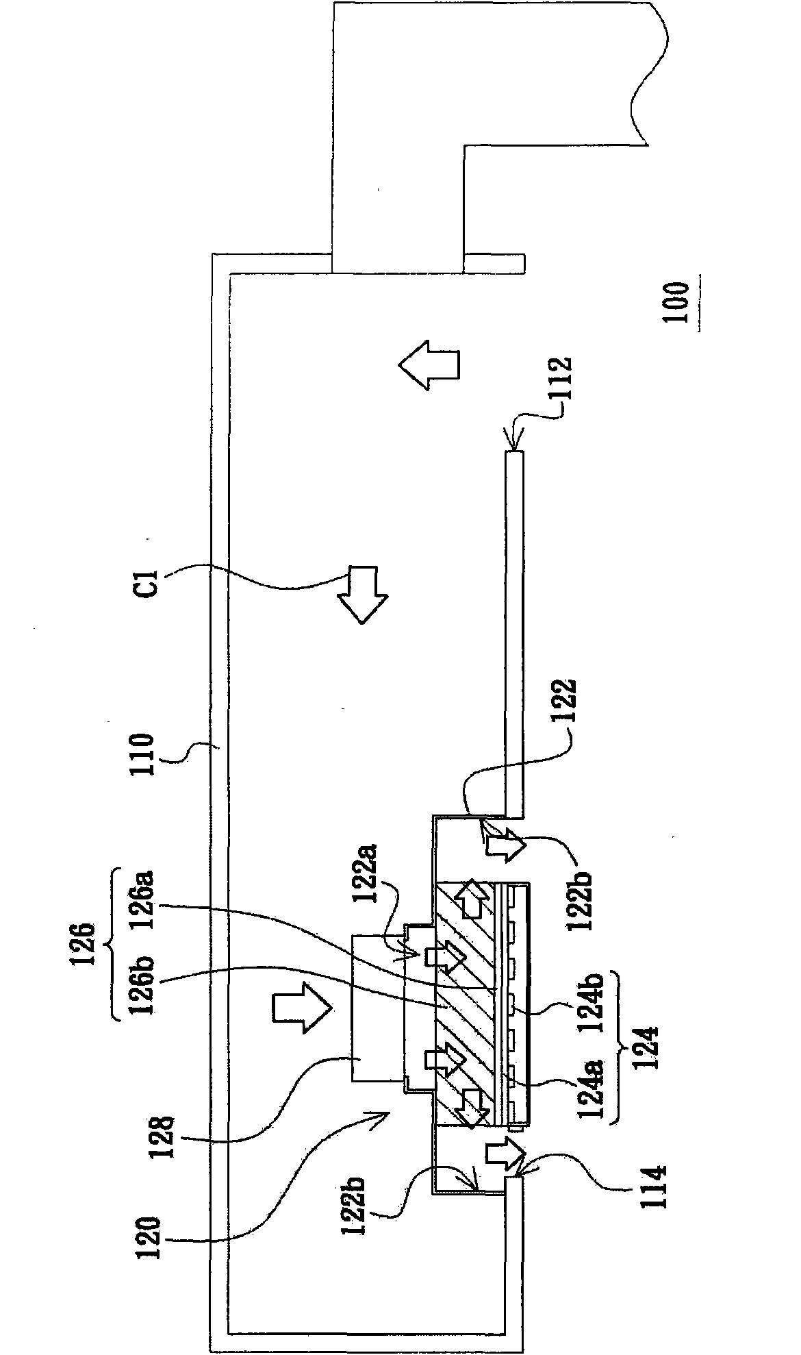
[0006] However, when the airflow generator 128 fails, the heat generated by the LED elements 124b cannot be effectively transferred to the external environment, so the lighting module 120 will be damaged due to excessive temperature.

Method used


Image

  • Illumination system
  • Illumination system
  • Illumination system

Examples


no. 1 example

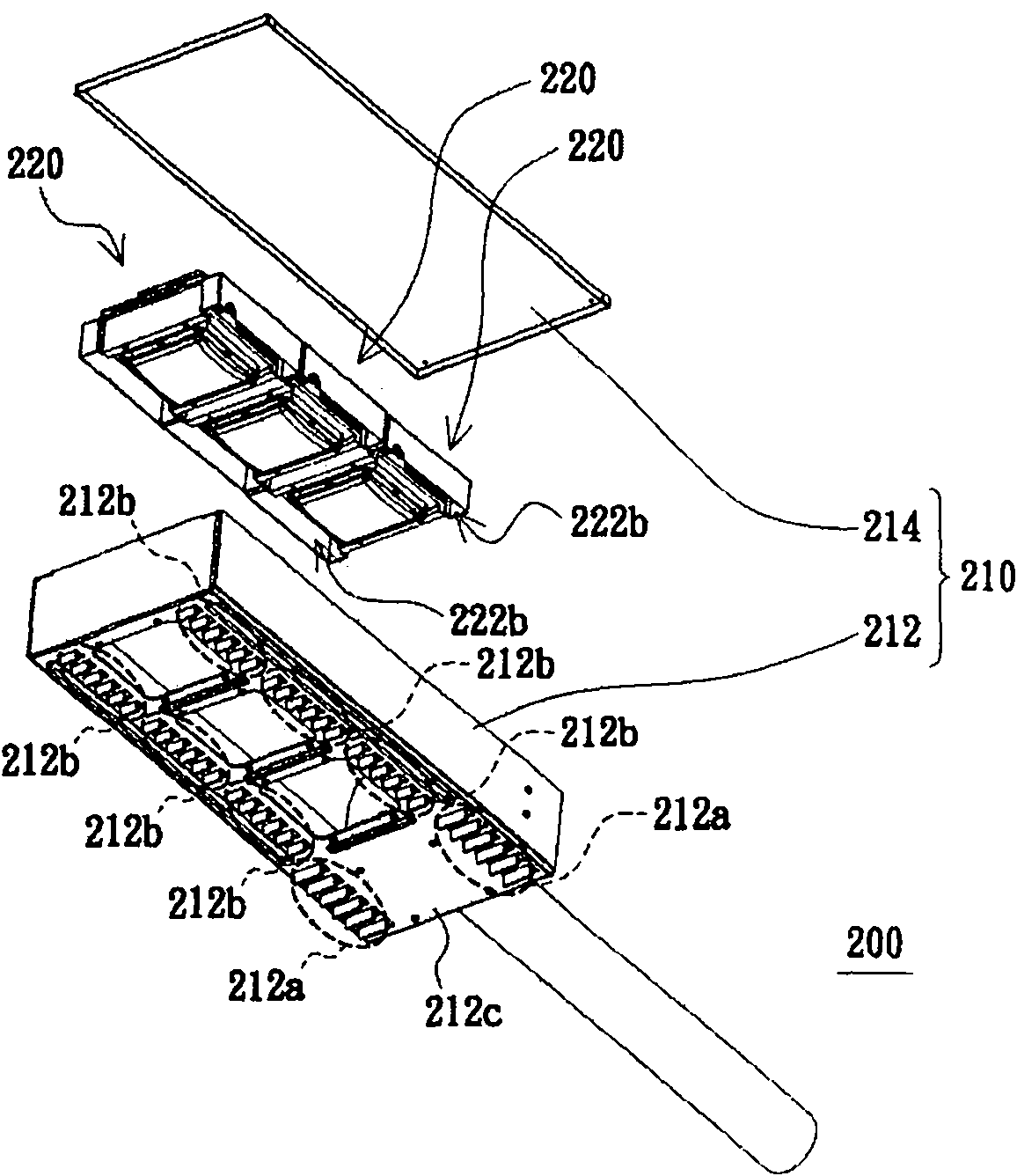
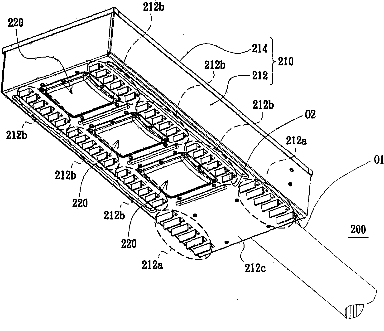
[0030] figure 2 A three-dimensional exploded schematic view of a lighting system according to the first embodiment of the present invention is shown. image 3 draw figure 2 A three-dimensional composite diagram of the lighting system. Figure 4 draw image 3 A schematic top view of the lighting system. Please refer to Figure 2 to Figure 4 , the lighting system 200 of this embodiment includes a system housing 210 and a plurality of lighting modules 220 . The system housing 210 includes a body 212 and a top cover 214 . The main body 212 has at least one first tuyere area 212a, a plurality of second tuyere areas 212b and a bottom plate 212c. The bottom plate 212c and the top cover 214 are opposite to each other. Each first tuyere area 212a has a plurality of first tuyere O1, and each second tuyere area 212b has a plurality of second tuyere O2. The first tuyeres O1 and the second tuyeres O2 are disposed on the bottom plate 212c and pass through the bottom plate 212c. In...

no. 2 example

[0044] Figure 9 A schematic top view of an illumination system according to a second embodiment of the present invention is shown. Please refer to Figure 9 The difference between the lighting system 300 of this embodiment and the lighting system 200 of the first embodiment is that the first tuyere area 312a and the second tuyere areas 312b of the system housing 310 of this embodiment are arranged in sequence along the axis A2 .

[0045] In summary, the lighting system of the embodiment of the present invention has at least one of the following or other advantages:

[0046] 1. When the lighting system of the embodiment of the present invention is not working normally, the distance between the second tuyere area corresponding to the lighting module with the abnormally operating airflow generator and the second tuyere area corresponding to the adjacent lighting module shorter. Therefore, the heat generated during the operation of the lighting module with the abnormally oper...


PUM


Abstract

The invention discloses an illumination system. The illumination system comprises a system shell and a plurality of illumination modules, wherein the system shell is provided with a first wind gap area and a plurality of second wind gap areas; one of two adjacent second wind gap areas between which a first distance is reserved is a second distance away from the first wind gap area; the other one of the two adjacent second wind gap areas between which the first distance is reserved is a third distance away from the first wind gap area; the first distance is less than the second distance and the third distance; each illumination module is arranged in the system shell and comprises guide shells, a light source, a radiating piece and an airflow generator; each guide shell is provided with a third air gap area and fourth air gap areas; the third air gap area is positioned inside the system shell and communicated with the first air gap area; and the second air gap areas between which the first distance is reserved correspond to and are communicated with the fourth air gap areas of different illumination modules respectively.

Description

technical field [0001] The present invention relates to a lighting system, and in particular to a configuration of a tuyere area of ​​the lighting system. Background technique [0002] Please refer to figure 1 , figure 1 A schematic cross-sectional view of a known lighting system is shown. The known lighting system 100 includes a system housing 110 and a lighting module 120 . The system housing 110 has a first air inlet 112 and a first air outlet 114 . The lighting module 120 is disposed at the first air outlet 114 . [0003] The lighting module 120 includes a flow guide housing 122 , a light source 124 , a heat sink 126 and an axial fan 128 . The air guide housing 122 has a second air inlet 122a and two second air outlets 122b. The second air outlets 122b correspond to the first air outlets 114, and the airflow generator 128 is disposed at the second air inlet 122a. The light source 124 includes a circuit board 124a and a plurality of LED elements 124b. The LED elem...

Claims


Application Information

Patent Timeline
Patent Type & Authority Applications(China)
IPC IPC(8): F21S2/00F21V15/02F21V29/02F21V23/00F21Y101/02F21V29/60F21V29/76
Inventor 许年辉
Owner YOUNG GREEN ENERGY
Learn More