Linked contact switch structure

A contact switch and linkage technology, which is applied in the direction of electric switches, electrical components, circuits, etc., can solve the problem that multiple contact switches cannot be linked 100 times

Inactive Publication Date: 2010-12-29
KUNDA COMP TECHKUSN
View PDF0 Cites 4 Cited by
  • Summary
  • Abstract
  • Description
  • Claims
  • Application Information

AI Technical Summary

Problems solved by technology

[0003] However, each of the buttons 200 is in one-to-one correspondence with each of the contact switches 100, and pressing a certain butto...

Method used


Image

  • Linked contact switch structure
  • Linked contact switch structure
  • Linked contact switch structure

Examples


Embodiment Construction

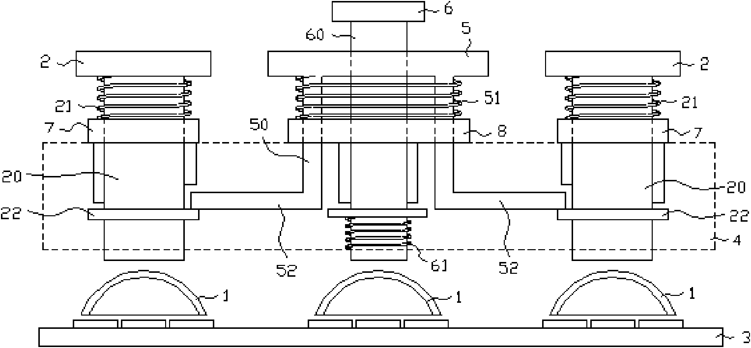
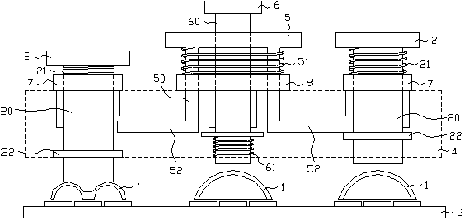
[0018] see figure 2 , figure 2 It is a side view of an unpressed state of a preferred embodiment of the linkage contact switch structure of the present invention.

[0019] The linkage contact switch structure provided by the present invention is provided on the circuit board 3 and the housing 4 of the electronic product. In this embodiment, the structure includes:

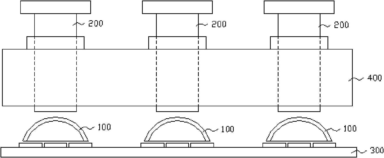
[0020] Three contact switches 1, the three contact switches 1 are arranged on the circuit board 3 and arranged on the same straight line;

[0021] Two side buttons 2, which respectively include a side pressing body 20 pierced through the above-mentioned shell 4 and a side spring 21 arranged between the side pressing body 20 and the surface of the shell 4, each side pressing body 20 is close to the bottom position A slave linkage side 22 is provided, and the bottom of each side pressing body 20 is correspondingly arranged above one of the contact switches 1 at the two ends;

[0022] A linkage button 5, which in...


PUM


Abstract

The invention provides a linked contact switch structure, which comprises three contact switches, two side buttons, a linked button and a central button, wherein the three contact switches are arranged on the circuit board and arranged in the same line; each side button has a side pressing body inserted into a shell and a side spring arranged between the side pressing body and the surface of the shell, and a linked edge is arranged at a position close to the bottom part of the side pressing body; the linked button comprises a linking body inserted into the shell and a linking spring arranged between the linking body and the surface of the shell, and the linking body comprises two linking edges extending to a place above the linked edge; and the central button comprises a central pressing body inserted into the linking body and a central spring arranged between the central pressing body and the bottom face of the shell. The linked contact switch structure can be used to link different contact switches.

Description

【Technical field】 [0001] The invention relates to a linkage contact switch structure, in particular to a linkage contact switch structure capable of performing combined operations on different contact switches. 【Background technique】 [0002] Contact switches are push button switches and are widely used in electronic products. see figure 1 , figure 1 It is a side view of the pressing structure of the prior art contact switch. The current common method is to arrange several contact switches 100 on the circuit board 300 of the electronic product, and the housing 400 of the electronic product is provided with buttons 200 corresponding to each of the contact switches 100 one by one. The button 200 can further make the corresponding contact switches 100 be pressed to be in an open state, so as to achieve the operation of the electronic product. [0003] However, each button 200 corresponds to each contact switch 100 one by one, and pressing a certain button 200 can only opera...

Claims


Application Information

Patent Timeline
IPC IPC(8): H01H9/26H01H13/70
Inventor 许世法
Owner KUNDA COMP TECHKUSN
Why Eureka
Try Eureka