Drilling device and method for metal doors and windows

A metal door and window and drilling device technology, which is applied in the field of door and window processing, can solve the problems of unfavorable cost control of production enterprises, reduced production efficiency, and high manual labor intensity, and achieve the effect of drilling operations at fixed positions

Active Publication Date: 2022-06-03
徐州科美瑞门窗科技有限公司
View PDF8 Cites 0 Cited by
  • Summary
  • Abstract
  • Description
  • Claims
  • Application Information

AI Technical Summary

Problems solved by technology

[0003]When the existing metal doors and windows are punched, the motor drives the drill bit to rotate the hole. At the same time, the cylinder moves the motor up and down to realize the drill bit’s up and down movement. Metal doors and windows are opened, but because different types of metal doors and windows have different opening positions, it is necessary to manually move the metal doors and windows back and forth to locate the opening positions, which requires a lot of manpower and time. The reduction of efficiency is not conducive to the cost control of production enterprises

Method used


Image

  • Drilling device and method for metal doors and windows
  • Drilling device and method for metal doors and windows
  • Drilling device and method for metal doors and windows

Examples


Embodiment 1

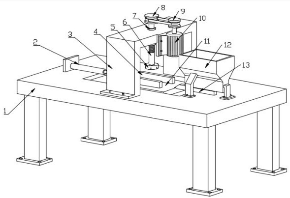
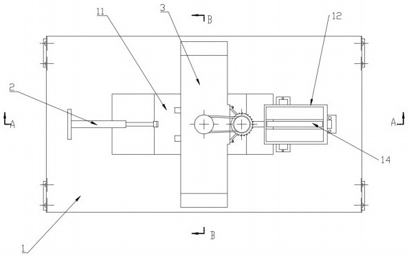
refer to Figure 1~Figure 4 , in this embodiment, a drilling device for metal doors and windows is proposed, which is used to drill holes for metal door and window lattice rods, and the drilling device for metal doors and windows includes:

The workbench 1 may be a rectangular plate-like structure, and a placement station and a processing station are arranged on the workbench 1 . Workbench 1 is used for support and installation. The bottom of the workbench 1 can be provided with support legs, the bottom of the support legs is fixedly provided with a backing plate, and the backing plate is provided with through holes through which bolts can pass through the workbench 1 to fix the workbench 1 on the ground or an assembly line. Of course, the bottom of the support leg can also be provided with a rotating wheel, a universal wheel, or a combination of the two, and the rotating wheel and / or the universal wheel are provided with a clamping plate for braking, so as to facilitate the m...

Embodiment 2

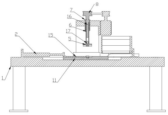
refer to Image 6 , in this embodiment, a drilling method for metal doors and windows is proposed, comprising the following steps:

S1 , the push-pull member pushes the sliding table 11 into the placement station, and the window lattice rod 14 falls on the sliding table 11 .

[0034] S2. The push-pull member pulls the sliding table 11 to move toward the processing station, and the transmission structure 15 drives the clamping rod 4 to move closer, and the clamping rod 4 moves closer to clamp the window mullion rod 14 .

[0035] S3. Determine the pressure F of the clamping rod 4 1 is greater than a preset F 1标 , if yes, execute S4.

[0036] S4, the distance sensor detects that the distance from the end of the window lattice rod 14 is L 0 .

[0037] S5, according to a preset punching position L i Control the push-pull member to move the sliding table 11, and the moving distance is L 0 +L i .

[0038] S6. The rotating driving member drives the polygonal rod 16 to drive th...


PUM


Abstract

The invention relates to the technical field of door and window machining, and discloses a drilling device and method for metal doors and windows, and the drilling device for the metal doors and windows comprises a sliding table which is slidably arranged on the upper surface of a workbench. The push-pull piece is installed on the workbench. The two clamping rods are oppositely located on the sliding table in a sliding mode. And the drilling pressing piece is mounted on the workbench. The first pressure sensor is used for sensing the pressure of the lifting rod. The second pressure sensor is used for sensing the clamping force of the clamping rod. The distance sensor is used for sensing the end distance of the window lattice rod. The controller is used for controlling the push-pull piece to push the sliding table to enter the placing station, and the window lattice rod falls on the sliding table; the push-pull piece pulls the sliding table to move towards the machining station, the clamping rods are driven by the transmission structure to be close to each other, and the clamping rods are close to clamp the window lattice rod; and quantitative drilling and moving are carried out. Window lattice rods are clamped and pushed in a linkage mode, and fixed-position punching operation is achieved through pressure and size control.

Description

technical field [0001] The invention relates to the technical field of door and window processing, in particular to a drilling device and method for metal doors and windows. Background technique [0002] With the acceleration of urbanization in recent years and the rapid development of the construction industry, the demand for metal doors and windows is also increasing. During the production process of metal doors and windows, some standard holes such as keyholes and cat's eye holes need to be correspondingly opened, which is convenient for subsequent adjustment. Its assembly lock and cat's eye needs. [0003] When the existing metal doors and windows are punched, the motor drives the drill to rotate and punch the holes, and at the same time, the cylinder pushes the motor to move up and down to realize the up and down movement of the drill to complete the opening of the metal doors and windows. Different, it is necessary to manually move the metal doors and windows back and...

Claims


Application Information

Patent Timeline
Patent Type & Authority Applications(China)
IPC IPC(8): B23B41/00B23B47/00B23Q3/06B23Q15/14B23Q17/00
CPCB23B41/00B23B47/00B23Q3/06B23Q17/00B23Q15/14Y02P70/10
Inventor 张建王山王丹丹
Owner 徐州科美瑞门窗科技有限公司
Why Eureka
Try Eureka