A new type of sunflower disc thresher

A sunflower tray and thresher technology, applied in threshing equipment, agricultural machinery and implements, applications, etc., can solve the problems of increasing manpower burden, loss of reuse value, inconvenient mixing and separation of flower trays and sunflower seeds, saving manpower, The effect of light weight and simple structure

Pending Publication Date: 2018-11-27
TIANJIN CHENGJIAN UNIV
View PDF0 Cites 0 Cited by
  • Summary
  • Abstract
  • Description
  • Claims
  • Application Information

AI Technical Summary

Problems solved by technology

[0003] The purpose of this invention is to provide a new type of sunflower disc thresher, which solves the problem that the crushed sunflower disc loses its reuse value on the one hand, and on the other hand it is inconvenient to mix and separate the crushed sunflower disc and sunflower seeds. Broken sunflower discs are directly dumped on the road and need to be collected manually, which increases the labor burden

Method used


Image

  • A new type of sunflower disc thresher
  • A new type of sunflower disc thresher
  • A new type of sunflower disc thresher

Examples


Embodiment 1

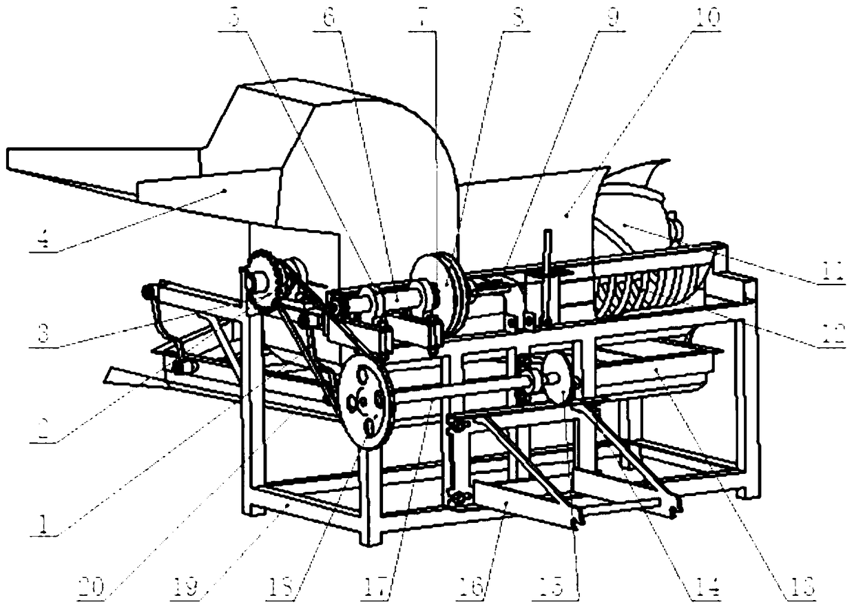
[0037] Such as figure 1 Shown, a kind of novel sunflower dish threshing machine, described threshing device comprises the compound drum that is made of loam cake 10, roller shaft 11 and lower cap 30, and described loam cake 10 upper end is provided with feed inlet 4, and described The surface of the roller shaft 11 is provided with a spiral keyway, the inner walls of the upper cover 10 and the lower cover 30 are provided with grid grooves 12, and the bottom of the lower cover 30 is provided with a leakage hole and a discharge port 33; The roller shaft one 11 passes through both sides of the compound drum, and is provided with a secondary primary pulley 2 at one end thereof, and a pinion 22 and a large sprocket are provided at the tail end of the secondary primary pulley 2;

[0038]Described driving device comprises clutch 9, power pulley 8 and a shaft 6, and described frame 19 is provided with a shaft 6 bearing seat 5, and described bearing seat is provided with a shaft 6, and...

Embodiment 2

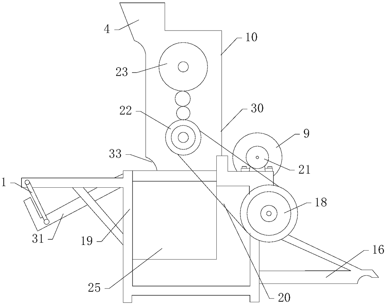
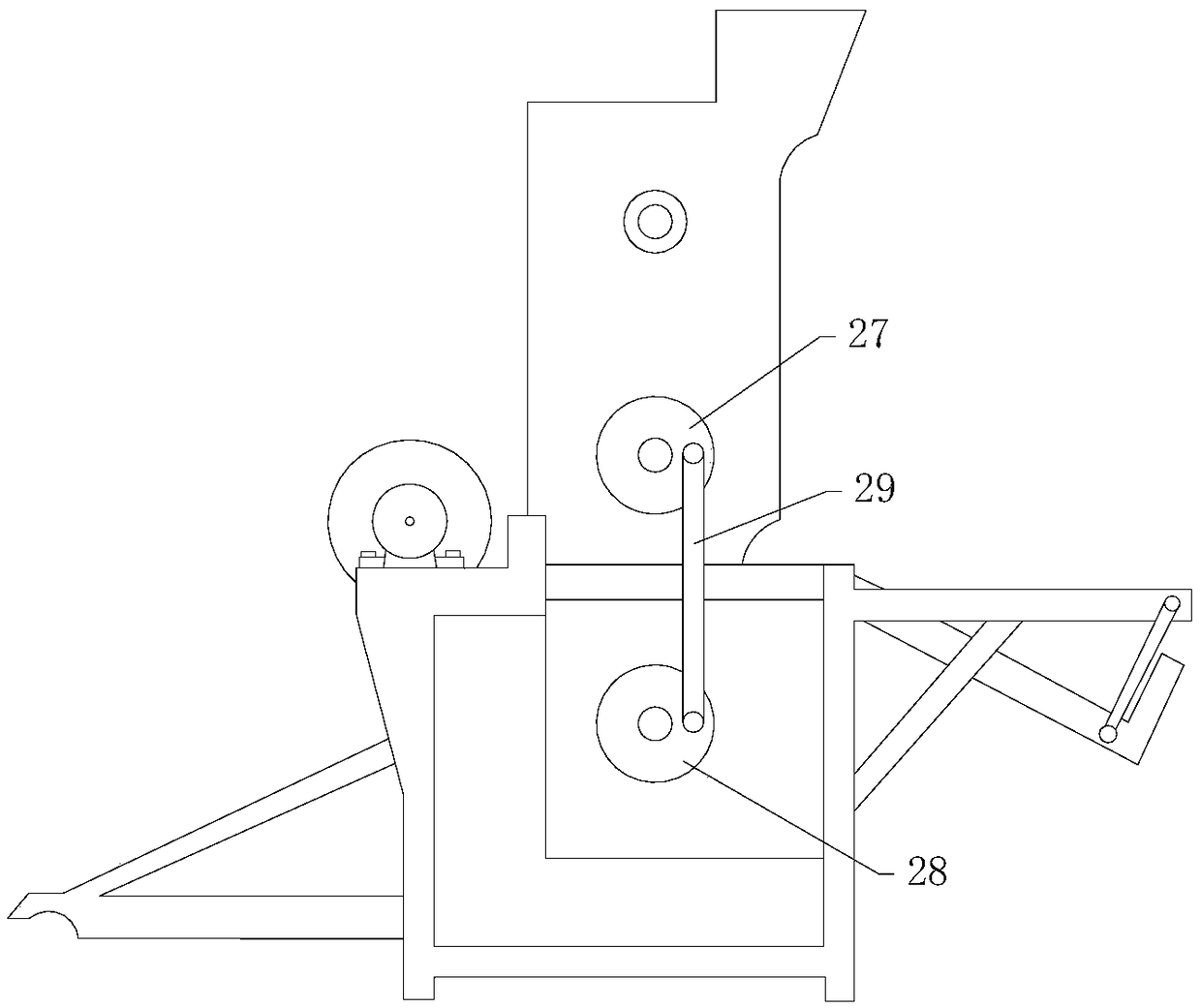
[0044] Such as Figure 2-6 As shown, the threshing device also includes a guide plate 24 and a roller shaft two 32, the roller shaft two 32 is aligned above the roller shaft one 11, and the guide plate 24 is set between the roller shaft one 11 and the roller shaft two 32;

[0045] The upper end of the guide plate 24 is connected with the upper left end of the upper cover 10, and the lower end of the guide plate 24 is in contact with the delivery tube roller, and is connected with the upper left end of the lower cover 30. The upper cover 10, the guide plate 24 and the lower cover 30 are connected from the upper Form a coherent cabin until the next connection;

[0046] Described drive device also comprises to bull gear 23, and one end of described roller shaft 2 32 is provided with bull gear 23, and the position of this bull gear 23 is on the same side as pinion 22, and described bull gear 23 and pinion 22 are meshingly connected , to achieve synchronous reverse rotation, the l...


PUM


Abstract

The invention discloses a novel sunflower disc thresher, which comprises a compound drum composed of an upper cover, a roller shaft and a lower cover. A clutch, a power belt pulley and a shaft are respectively provided with a stop gear and a clutch at two ends of the shaft, the first shaft and the power belt pulley are connected through angular contact ball bearings, the second master belt pulleyis connected with the chain of the second slave belt pulley, the stop gear is meshed with the chain, a double-layer sieve bed, a crank disk and a connecting rod are arranged at one end of the shaft; Alow part of that lower cov is provided with a double-layer sieve bed, one end of the double-layer sieve bed is provided with a connecting rod, the connecting rod is connecte with a crank plate through a sieve bin, one end of the crank plate is provided with three shafts and a two-stage driven belt pulley, and the two-stage driven belt pulley is connected with the two-stage driving belt pulley through a belt, so as to realize synchronous operation. As that sunflower disk of the invention is thresh by the double-type drum, the integrity of the disk can be almost preserved, the utilization rateof the sunflower disk in the lat stage is improved, and the sunflower disk is convenient to dry. But also facilitate the screening and separation of sunflower seeds.

Description

technical field [0001] The invention belongs to the field of agricultural by-product processing machinery, and in particular relates to a novel sunflower disc thresher. Background technique [0002] Sunflower seeds, the fruit of the sunflower, can be used for food and oil. Sunflower seeds are rich in unsaturated fatty acids, multivitamins and trace elements, plus their delicious taste, so they become a very popular snack and edible oil source. The existing product is driven by a motor, which directly drives the roller shaft to rotate after a first-stage belt deceleration, but the tractor-powered threshing machine has a complicated structure, with a conveyor belt from low to high. Although the conveyor belt saves people from bending over to pick sunflowers, But without adding automation, the sunflower discs are crushed during threshing, and the dregs and sunflower seeds are separated. On the one hand, the crushed sunflower discs lose their reuse value, and on the other hand,...

Claims


Application Information

Patent Timeline
IPC IPC(8): A01F11/00A01F12/20A01F12/44A01F12/58A01F12/00
CPCA01F11/00A01F12/00A01F12/20A01F12/446A01F12/58Y02P60/14
Inventor 张婧张忠海汪文津赵坚李琎
Owner TIANJIN CHENGJIAN UNIV
Why Eureka
Try Eureka