Submersible mixer with cutting function
A submersible mixer, belt cutting technology, applied in the direction of aerobic process treatment, sustainable biological treatment, etc., can solve the problems of easy entanglement of dirt fibrous dirt, easy entry of particulate impurities, easy damage of mechanical seals, etc., to achieve mechanical seal Good, prevents dirt from entanglement, and protects mechanical seals
- Summary
- Abstract
- Description
- Claims
- Application Information
AI Technical Summary
Problems solved by technology
Method used
Image

Examples
Embodiment 1
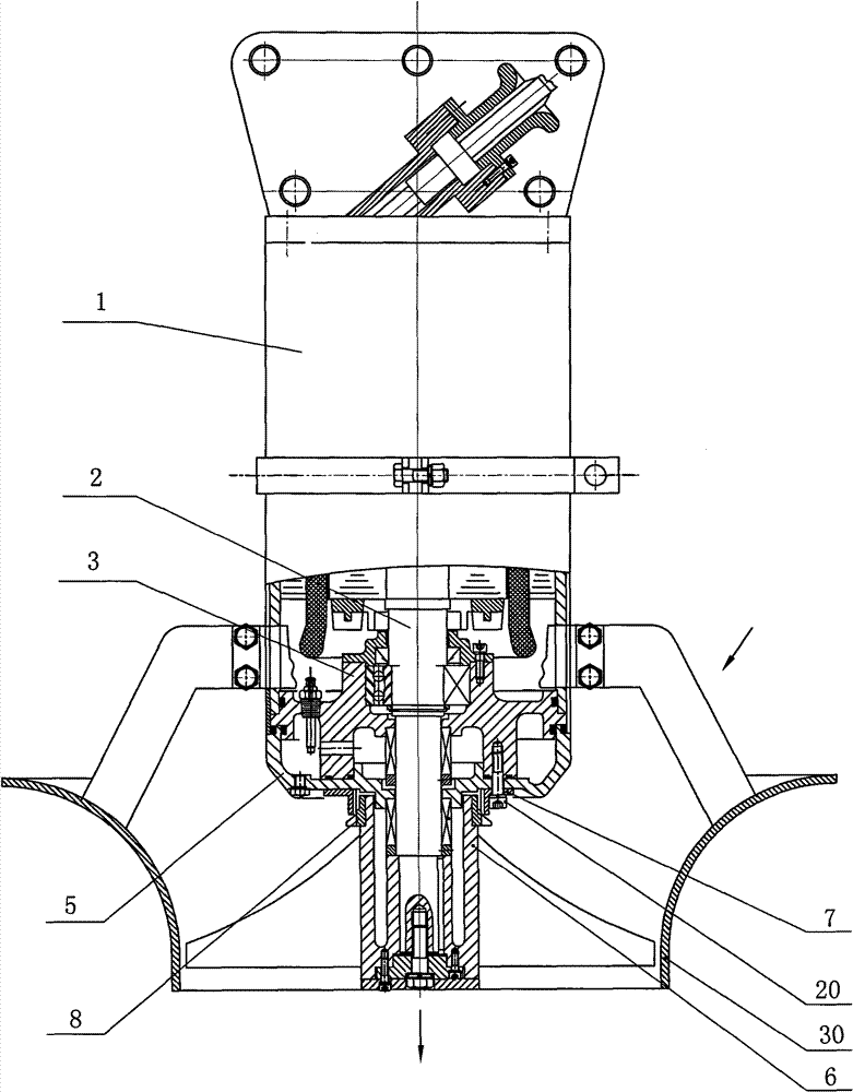
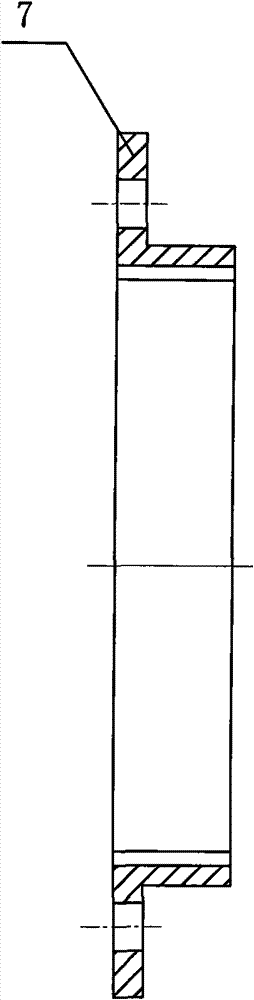
[0022] like figure 1 Shown: the preferred embodiment 1 of the present invention includes a submersible motor 1, a rotating shaft 2 arranged at the output shaft end of the submersible motor 1, a bearing seat 3 arranged on the outer circumference of the rotating shaft 2, a mechanical seal seat 5 arranged below the bearing seat 3, and the rotating shaft 1. The fixedly connected propeller 6 also includes a cutting device. The cutting device is composed of a fixed knife 7 and a rotating knife 8 that fit in clearance. The fixed knife 7 is arranged on the mechanical seal seat 5, and the rotating knife 8 is arranged on the propeller 6. The area is located at the inlet of the propeller 6 .
[0023] The fixed knife 7 is connected with the mechanical seal seat 5 and the bearing seat 3 through the screw 20, and the rotary knife 8 is connected with the propeller 6 through a tight fit. The propeller 6 is coaxial with the submersible motor 1. When working, the submersible motor 1 drives the ...
Embodiment 2
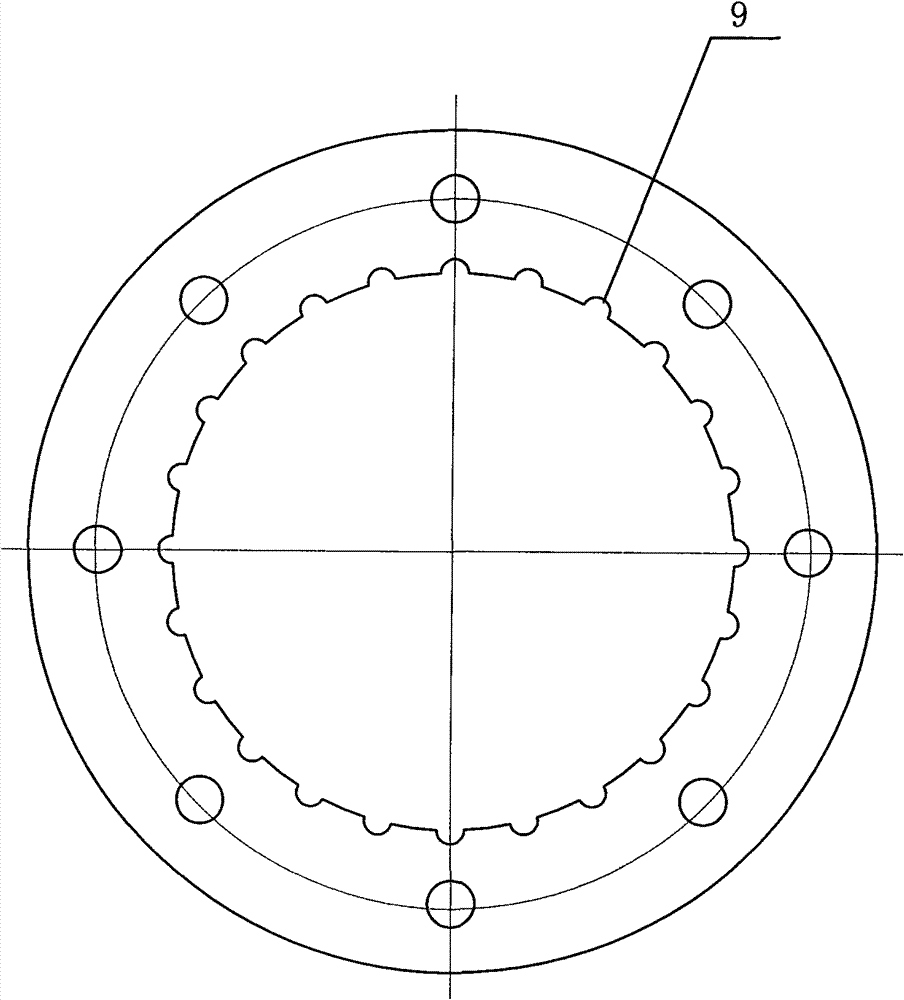
[0025] Preferred Embodiment 2 of the present invention: the basic structure is the same as that of the preferred embodiment 1, the difference is that the number of cutting grooves 9 is 18, the number of water passages 10 on the rotary knife 8 is 5, and the shafts of the guide rings 11 and 12 are The inclination angle is 50°.
Embodiment 3
[0026] Preferred Embodiment 3 of the present invention: the basic structure is the same as that of the preferred embodiment 1, the difference is that the number of cutting grooves 9 is 24, the number of water passages 10 on the rotary knife 8 is 5, and the shafts of the guide rings 11 and 12 are The inclination angle is 60°.
[0027] In the present invention, since the fixed knife 7 and the rotary knife 8 are matched with a gap, and the gap is small, before the dirt enters the inlet side of the propeller 6, the guide rings 11 and 12 of the rotary knife 8 are first introduced into the cutting area and cut, and the fixed knife The number of cutting grooves 9 on 7 is relatively large, ranging from 12 to 24, and the number of water passing grooves 10 on the rotary knife 8 is 3 to 5. Therefore, the dirt of the present invention is cut more than 300 times per second, so The cutting effect is good, and the dirt is effectively chopped, thereby effectively preventing the dirt from wrap...
PUM
 Abstract
Description
Claims
Application Information
 - R&D Engineer
- R&D Manager
- IP Professional
- Industry Leading Data Capabilities
- Powerful AI technology
- Patent DNA Extraction
Browse by: Latest US Patents, China's latest patents, Technical Efficacy Thesaurus, Application Domain, Technology Topic.
© 2024 PatSnap. All rights reserved.Legal|Privacy policy|Modern Slavery Act Transparency Statement|Sitemap