
Die device in section punching machine

A punching machine and profile technology, applied in the field of punching die devices, can solve the problems of low production efficiency, the speed of punching cannot be synchronized with the production line, and affect production efficiency, so as to achieve the effect of improving production efficiency

Inactive Publication Date: 2013-02-13
ZHANG JIAGANG BAIXIONG KLIMENS MACHINERY
View PDF0 Cites 0 Cited by
  • Summary
  • Abstract
  • Description
  • Claims
  • Application Information

AI Technical Summary

Problems solved by technology

Because the upper template can only move in one direction under the drive of the transmission device, it can only punch holes on one side of the profile. When the other side of a profile also needs to be punched, it must be punched on one side first, and then turned over manually. Then punch the other side
In this way, the production efficiency is low, especially when the punching machine is used in conjunction with the profile production line, because manual steering is required to realize multi-sided punching, the punching speed cannot be synchronized with the production speed of the production line, which greatly affects the production efficiency

Method used


Image

  • Die device in section punching machine
  • Die device in section punching machine
  • Die device in section punching machine

Examples


Embodiment Construction

[0017] The die device in the profile punching machine of the present invention will be further described in detail below through specific examples.

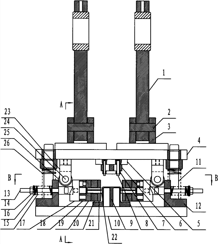
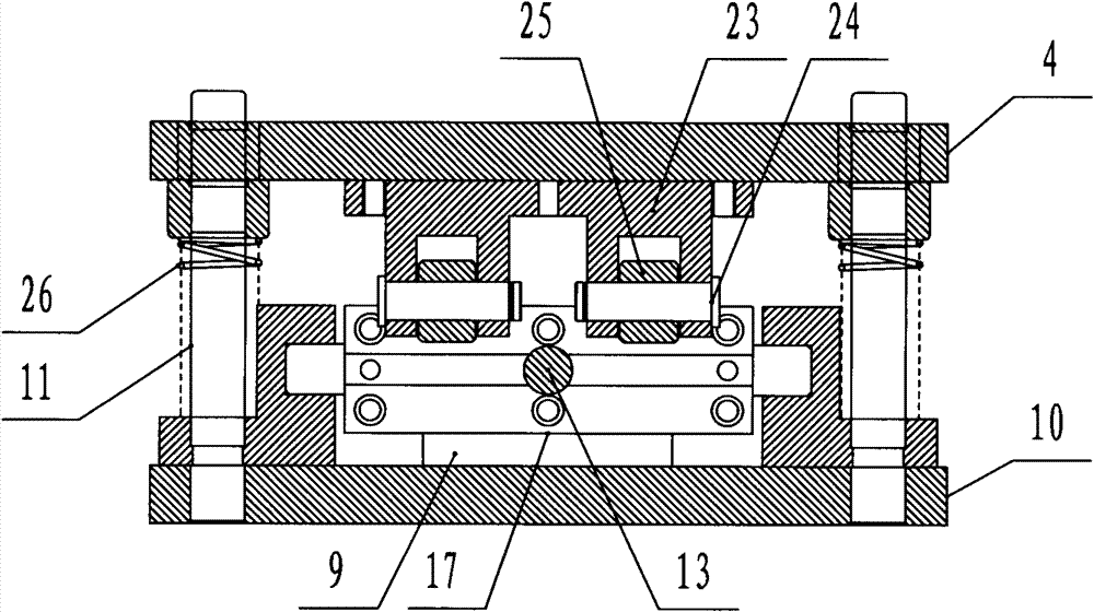
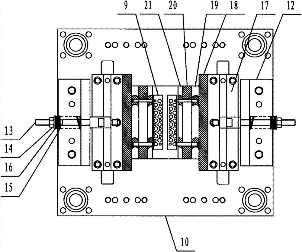
[0018] Such as figure 1 , figure 2 As shown, the die device in the profile punching machine includes: two crank arms 1 connected to the transmission device in the profile punching machine, and the lower ends of the two crank arms 1 are connected to the fork seat 3 through the crank arm shaft 2 respectively. connection, each fork seat 3 is fixed with the upper template 4, the lower part of the upper template 4 is connected with an upper fixed plate 5, the upper fixed plate 5 is connected with the upper buffer plate 6, and the upper buffer plate 6 is connected with the upper discharge plate 7 connection, the lower part of the upper fixing plate 5 is fixed with an upper punch 8, and the lower part of the upper punch 8 is provided with a corresponding mold 9, and the mold 9 is arranged on the top of the lower template 10, and the u...


PUM


Abstract

The invention relates to a die device in a section punching machine. The die device comprises a crank arm connected with a transmission device of the section punching machine; the crank arm is connected with an upper template; the lower part of the upper template is connected with an upper punch; a mould is arranged below the upper punch and on the upper part of a lower template; a guide post and a horizontal die device are arranged between the upper template and the lower template; the horizontal die device comprises a backup plate on the lower template; a punch pull rod is penetrated through the backup plate; a clamp nut is fixed at one end of the punch pull rod; a punch reset spring is arranged on the punch pull rod between the clamp nut and the backup plate; the other end of the punch pull rod is connected with a movable plate; the outer side surface of the movable plate is a bevel; the movable plate is connected with a horizontal punch; the lower part of the upper template is connected with a press roller seat; and a press roller is arranged in the press roller seat and positioned right above the bevel of the movable plate. The invention is applicable to the section punching machine and can implement synchronous punching of at least two side surfaces of the section.

Description

technical field [0001] The invention relates to the technical field of punching machines, in particular to a die device in a profile punching machine. Background technique [0002] The structure of the currently used profile punching machine is as follows: it includes a base, a frame is fixed on the base, a power device is fixed on the frame, the power device is connected with the transmission device, and the transmission device drives the die device to perform punching work. The punching die device includes an upper template and a lower template, and the upper template is connected with a transmission device. When working, put one side of the profile to be punched on the mold on the lower template, the power device drives the upper template to move up and down through the transmission device, and the punch installed on the upper template punches the profile, so as to achieve the purpose of punching. Because the upper template can only move in one direction under the drive ...

Claims


Application Information

Patent Timeline
Patent Type & Authority Patents(China)
IPC IPC(8): B21D28/34
Inventor 龚凯杨生严
Owner ZHANG JIAGANG BAIXIONG KLIMENS MACHINERY
Learn More