
Online synchronous film leftover recycling device

A technology of recycling device and rewinding device, which is applied in thin material handling, transportation and packaging, winding strips, etc., can solve the problems of increased mechanical wear, uneven force, and no improvement of film utilization rate, and achieves improved utilization. The effect of synchronization of production rate and production speed

Inactive Publication Date: 2014-05-28
苏州梦工坊信息科技有限公司
View PDF6 Cites 6 Cited by
  • Summary
  • Abstract
  • Description
  • Claims
  • Application Information

AI Technical Summary

Problems solved by technology

[0004] The first one is to directly inhale the melting hopper through the exhaust fan, and after melting and cooling, it will be transformed into granular raw materials and put into the production line for reuse. Single, does not improve the utilization rate of the produced film, not the first choice of small manufacturers
The second recycling method is to repeatedly fold and accumulate the side materials through the mechanism. This method is simple and easy to implement, but it ignores the irregularity and elasticity of the side materials, resulting in loose accumulation and high piles that are easy to fall.
[0005] According to the packaging film waste recycling device published in Chinese patent 01207961.8, it includes: a machine base, a driving device, a recycling turntable, a movable reel, and a waste material sorting device; the driving device is located on a machine base for driving the waste sorting device and recycling turntable The driving device is connected to the driving device through a belt and a pulley to obtain rotational power; the problem in this technical solution is that the driving device uses a motor, which drives the recycling turntable to rotate through the belt and the pulley, the motor speed is fixed, and the speed generated by the waste film belt is determined by the production line The upper speed is determined and remains unchanged. With the increase of waste materials on the movable reel, the radius of the recycling turntable increases, and the rotation speed of the turntable cannot be changed, which makes the film side material belt more and more tightly wound, eventually leading to breakage, thus The resulting uneven force also increases mechanical wear

Method used


Image

  • Online synchronous film leftover recycling device
  • Online synchronous film leftover recycling device
  • Online synchronous film leftover recycling device

Examples


Embodiment 1

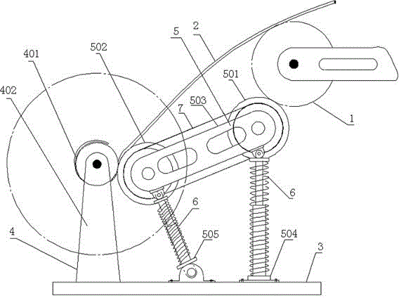
[0031] Both the active wheel bracket 504 and the driven wheel bracket 505 are liftable brackets, the bottom of the active wheel bracket 504 is fixedly connected to the base 3, and the bottom of the driven wheel bracket 505 is connected to the bottom of the driven wheel bracket 505. The base 3 is movably connected, and the top of the driven idler bracket 505 is connected with the second end of the idler link 503 .

[0032]The spring 6 includes a first spring and a second spring, the first spring is sleeved on the driving idler bracket 504, the second spring is sleeved on the driven idler bracket 505, and the first spring is sleeved on the driven idler bracket 505. The first ends of the spring and the second spring are fixedly connected with the base 3 respectively, the second end of the first spring is connected with the first end of the said wheel link 503, and the second end of the second spring is connected with the said wheel. The second end of the rod 503 is connected, and...

Embodiment 2

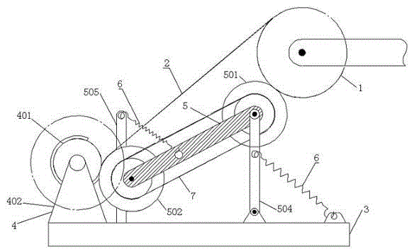
[0035] The bottom of the driving idler bracket 504 is movably connected with the base 3 , and the bottom of the driven idler bracket 505 is fixedly connected with the base 3 .

[0036] The spring 6 includes a first spring and a second spring, the first end of the first spring is connected with the active wheel support 504, and the second end is connected with the base 3; the first end of the second spring is connected with the The said idler link 503 is connected, the second end is connected with the top of the driven idler bracket 505, and the first spring and the second spring are both in tension state.

[0037] The distance from the first end of the first spring to the top of the driving wheel bracket 504 is less than the distance from the first end of the first spring to the bottom of the driving wheel bracket 504; The distance between the driving idler 501 is greater than the distance from the first end of the second spring to the driven idler 502 .

[0038] The distance...

Embodiment 3

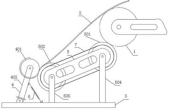
[0041] The bottoms of the driving idler bracket 504 and the driven idler bracket 505 are fixedly connected to the base 3 respectively, and the top of the driven idler bracket 505 is connected with the second end of the idler link 503, so that The bottom of the rewinding shaft support 402 is movably connected to the base 3, the first end of the spring 6 is connected to the rewinding shaft support 402, the second end is connected to the base 3, the first end of the spring 6 is connected to the rewinding shaft support The distance from the top of 402 is smaller than the distance from the first end of the spring 6 to the bottom of the winding shaft support 402, and the spring 6 is in a stretched state.

[0042] Since the bottom of the winding shaft support 402 is movable, the tension of the spring can make the edge of the winding shaft 401 abut against the driven roller 502 .

[0043] The present invention does not need a driving motor, and realizes synchronous recycling of the fi...


PUM


Abstract

The invention discloses an online synchronous film leftover recycling device which comprises a base, a winding mechanism, a transmission mechanism and at least one spring. The winding mechanism and the transmission mechanism are arranged on the base. The winding mechanism comprises a winding shaft. The transmission mechanism comprises a driving bearing wheel, a driven bearing wheel and a bearing wheel connecting rod. The driving bearing wheel and the driven bearing wheel are respectively mounted at two ends of the bearing wheel connecting rod and are in transmission connection through a transmission chain or cog belt. The driving bearing wheel is closely abutted to a driving roller, the driven bearing wheel is closely abutted to the winding shaft, the joints of the first ends of the springs are kept constant relative to the base, and the second ends of the springs are connected to the winding mechanism or the transmission mechanism. By the aid of the power of the driving roller of a winding device on a production line, film leftover recycling synchronous with the production line is realized, rotation speed of the winding shaft can be automatically controlled and is ensured to be synchronous with production speed of a film making machine.

Description

technical field [0001] The invention relates to an online synchronous recovery device for film edge material. Background technique [0002] In the factory plastic film production line, there will be uneven edges, or in the process of product packaging, waste film strips with uniform width will be cut out. These film scraps are flammable. If they cannot be disposed of in time, they will pile up in disorder on both sides of the production line, which will bring hidden dangers to safe production and occupy the space of the factory. Therefore, it is necessary to collect the scraps to keep the site clean and convenient. secondary use. [0003] There are currently several ways to collect scraps: [0004] The first one is to directly inhale the melting hopper through the exhaust fan, and after melting and cooling, it will be transformed into granular raw materials and put into the production line for reuse. Single, without improving the utilization rate of the produced film, it ...

Claims


Application Information

Patent Timeline
Patent Type & Authority Applications(China)
IPC IPC(8): B65H18/16B65H18/02
Inventor 吕明新李頔龠
Owner 苏州梦工坊信息科技有限公司
Learn More