Method and device for notifying handover failure indication information

A technology for indicating information and switching failures, applied in wireless communication, electrical components, connection management, etc., can solve problems such as wasting network resources and negative impact on user experience, and achieve the effects of saving network resources, improving success rate, and improving service quality

Active Publication Date: 2011-01-26
ADVANCED STANDARD COMM LLC
View PDF3 Cites 22 Cited by
  • Summary
  • Abstract
  • Description
  • Claims
  • Application Information

AI Technical Summary

Problems solved by technology

Improper handover parameter settings can lead to ping-pong handover, handover failure, and radio link failure (RLF), which are undesirable handovers that negatively impact user experience and waste network resources

Method used


Image

  • Method and device for notifying handover failure indication information
  • Method and device for notifying handover failure indication information
  • Method and device for notifying handover failure indication information

Examples


Embodiment 1

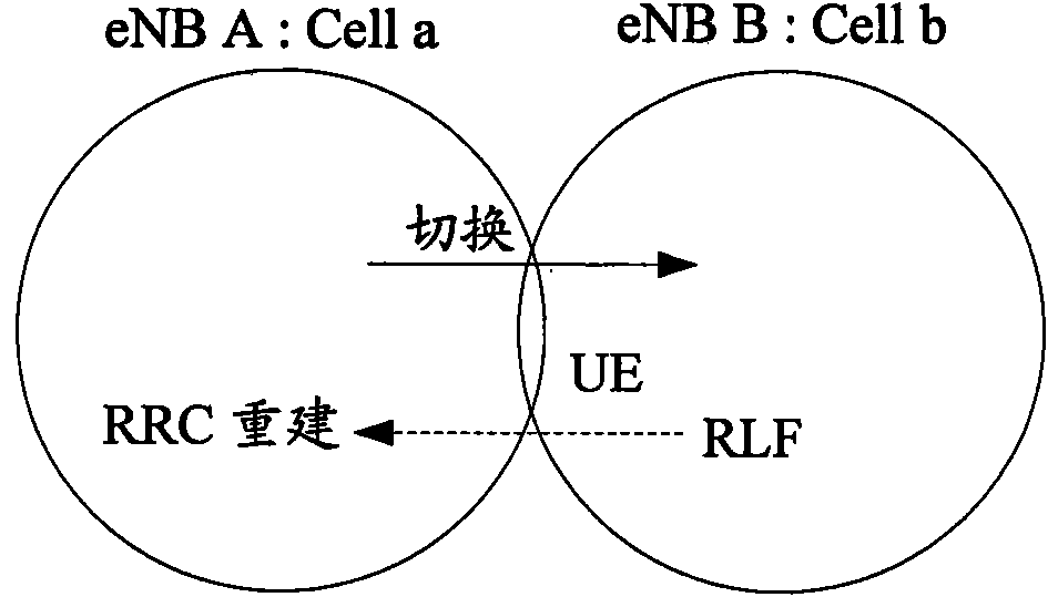
[0057] This example is for figure 1 The application scenario shown.

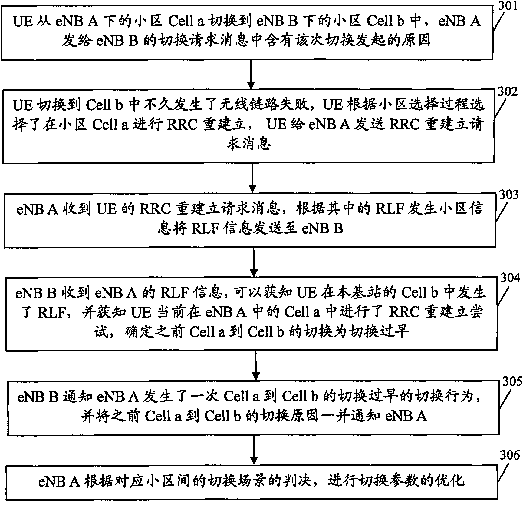
[0058] image 3 It is a flow chart of the method for notifying the cause of the handover when the UE is handed over from Cell a to Cell b too early in the present invention, such as image 3 As shown, in this example, when the UE switches from Cell a to Cell b too early, the method for notifying the cause of the handover includes the following steps:

[0059] Step 301: UE is handed over from Cell a under eNB A to Cell b under eNB B, and the handover request message sent by eNB A to eNB B contains the reason for this handover initiation. The UE located in Cell a determines to initiate a handover request to a neighboring cell (Cell b), or eNB A initiates a handover request to Cell b; (Cell b) measure the wireless signal strength and find that the wireless signal strength of the cell b meets the handover requirement, and initiate a handover request to the eNB B to the cell Cell b. Or, eNB A determines that ...

Embodiment 2

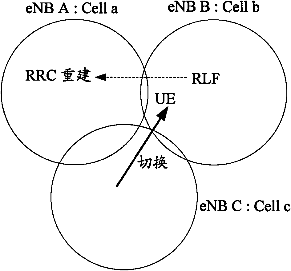
[0068] This example is for figure 2 The application scenario shown.

[0069] Figure 4 A flow chart of the method for notifying the cause of the handover when the UE switches from Cell c to Cell b in the present invention and selects a handover cell error, as shown in Figure 4 As shown, in this example, when the UE switches from Cell c to Cell b and selects a wrong cell to switch over, the method for notifying the cause of the handover includes the following steps:

[0070] Step 401: UE is handed over from Cell c under eNB C to Cell b under eNB B, and the handover request message sent by eNB C to eNB B contains the reason for this handover initiation. For the reason of switching, refer to the relevant description in step 301.

[0071] Step 402: The radio link failure occurs shortly after the UE switches to Cell b, the UE selects Cell a for RRC reestablishment according to the cell selection process, and the UE sends an RRC reestablishment request message to eNB A.

[007...


PUM


Abstract

The invention discloses a method for notifying handover failure indication information, comprising the following steps: a first base station determines the information of a cell where radio link failure (RLF) happens before radio resource control (RRC) rebuilding of user equipment via RLF information in received RRC rebuilding request information and transmits the RLF information to a second base station subordinate to the cell where RLF happens; and the second base station notifies a base station launching handover of the indication information of too early handover or wrong selected handover cell meeting the notification condition according to the notification condition of the set indication information of too early handover or wrong selected handover cell, or the second base station notifies the base station launching handover of the indication information of too early handover or wrong selected handover cell when determining that the scene handed over to the cell where RLF happens by the user equipment is too early in handover or wrong in selected handover cell. The invention simultaneously discloses a device of the method. The invention promotes the success rate of cell handover.

Description

technical field [0001] The present invention relates to handover technology of a user terminal, in particular to a method and device for notifying handover failure indication information in a Long Term Evolution (LTE, Long Term Evolution) system. Background technique [0002] The LTE network consists of an Evolved Universal Terrestrial Radio Access Network (E-UTRAN, Evolved Universal Terrestrial Radio AccessNetwork), an evolved base station (eNB, Evolved NodeB) and an evolved packet switching center (EPC, Evolved Packet Core). A collection of eNBs that are connected to the E-UTRAN and the EPC through the S1 interface, and the eNBs can be connected through the X2. S1 and X2 are logical interfaces. One EPC can manage one or more eNBs, one eNB can also be controlled by multiple EPCs, and one eNB can manage one or more cells. [0003] Self Organizing Network (SON, Self Organizing Network) is a technology for automatic network configuration and optimization. The feature of thi...

Claims


Application Information

Patent Timeline
Patent Type & Authority Applications(China)
IPC IPC(8): H04W36/00H04W88/08
CPCH04W36/0055H04W36/0079H04W36/0058H04W36/0072H04W68/005H04W68/02H04W76/27
Inventor 韩立锋
Owner ADVANCED STANDARD COMM LLC
Why Eureka
Try Eureka