Led module with optical diffusion layer formed

A technology of light-emitting diodes and light-diffusing layers, applied to semiconductor devices, light sources, electric light sources, etc. The effect of longevity

Inactive Publication Date: 2012-11-14
株式会社吉光 +1
View PDF1 Cites 0 Cited by
  • Summary
  • Abstract
  • Description
  • Claims
  • Application Information

AI Technical Summary

Problems solved by technology

[0004] However, the LED fluorescent lamps and LED BARs related to the above-mentioned prior art only display with the light or brightness of the LEDs. Therefore, a large amount of LEDs need to be consumed. In order to solve the heat generation problem caused by this, the weight of the heat dissipation plate will increase, resulting in In addition, after using a large number of LED light sources, the brightness is uneven, and the part with more LEDs will become too bright, while the part without LEDs will have a decrease in brightness, causing shadows. In order to eliminate the above shadows, It is necessary to arrange LEDs more densely, so that more LEDs are used, which increases the heat generation of LEDs and cannot give full play to the advantages of LEDs

Method used


Image

  • Led module with optical diffusion layer formed
  • Led module with optical diffusion layer formed
  • Led module with optical diffusion layer formed

Examples


Embodiment Construction

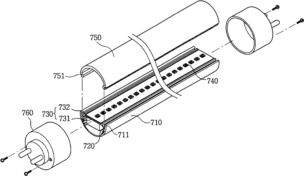
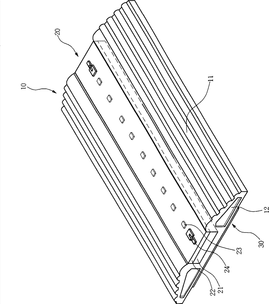
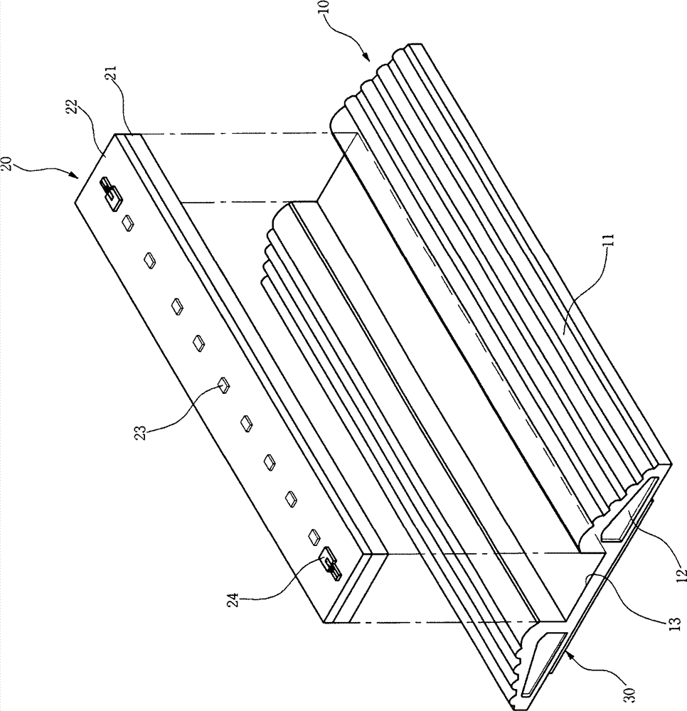
[0024] figure 2 It is a perspective view of an LED module formed with a light diffusion layer according to the present invention, image 3 It is an exploded view of an LED module formed with a light diffusion layer according to the present invention, Figure 4 It is a top view of an LED module formed with a light diffusion layer according to the present invention, Figure 5 It is a side view of an LED module formed with a light diffusion layer according to the present invention, Figure 6 yes Figure 5 The enlarged schematic diagram of part A in Figure 7 is a schematic diagram of the heat conduction direction of the heat dissipation diffusion plate involved in the present invention, Figure 8 It is the first embodiment of the LED module formed with the light diffusion layer according to the present invention, Figure 9 It is the 2nd Example of the LED module in which the light-diffusion layer was formed concerning this invention.

[0025] Hereinafter, the constituent p...


PUM


Abstract

The invention provides an LED module with an optical diffusion layer formed to serve as a mirror around LEDs for attaining irregular reflection of light by few LEDs so as to disperse the light from an angled layer for dispersing the light angle and to secondarily dispersing light from another irregular reflection layer, thereby uniformly distributing the light on a light emitting surface when using the LED as an illumination light source member. The LED module includes the optical diffusion layer formed to include a heat radiation diffusion plate having irregularly reflecting diffusion layersformed on its both sides and a U-shaped insertion port formed in its central upper end; a light emitting section having a PCB substrate coupled into the insertion port by a press-in method, a waterproof resin layer formed on an upper surface of the PCB substrate 21, input / output connectors for power supply formed on upper surface both ends of the waterproof resin layer and the LEDs3 longitudinally disposed between the input / output connectors; and a double-sided tape longitudinally attached to the bottom of the heat radiation diffusion plate to fix the heat radiation diffusion plate to a framewith a lid.

Description

technical field [0001] The invention relates to an LED (Light Emitting Diode) module formed with a light diffusion layer, in particular to an LED module formed with a light diffusion layer so as to greatly improve the light diffusion performance. Background technique [0002] Generally speaking, LED (Light Emitting Diode) is different from conventional lighting equipment such as incandescent lamps and fluorescent lamps. It has a high conversion efficiency from electric energy to light energy, up to 90%, which can greatly save energy. Or signboards, electro-optical panels and many other fields. [0003] Korean Registered Patent No. 10-0866586 (Title of Invention: Fluorescent Lamp Using LED), such as figure 1 As shown, its composition includes: a body 710, the body 710 has an extension part bent inwardly from both ends of the hemispherical substrate; a heat radiation blade 720, the heat radiation blade 720 is formed along the length direction inside the substrate of the body ...

Claims


Application Information

Patent Timeline
Patent Type & Authority Patents(China)
IPC IPC(8): F21S2/00F21V23/00F21V7/00F21V29/00F21V31/00
CPCF21V5/04F21V29/83F21V31/00F21Y2115/10Y10S362/80
Inventor 吉惠龙
Owner 株式会社吉光
Why Eureka
Try Eureka