Automatic zeroing method and equipment for incremental sensor

A sensor and incremental technology, applied in the direction of operation through zero adjustment, can solve the problems of wasting time and power, error-prone, low efficiency, etc., and achieve the effect of shortening redundant strokes and efficient automatic zero return

Active Publication Date: 2011-02-09
NANJING NAIERSI PHOTOELECTRIC INSTR
View PDF5 Cites 14 Cited by
  • Summary
  • Abstract
  • Description
  • Claims
  • Application Information

AI Technical Summary

Problems solved by technology

[0004] The disadvantage of the "manual judgment method" is that it must be operated by someone, which is inefficient, error-prone, and has high requirements for the operator. In addition, the site of many equipment is unmanned or difficult to reach, so it is only suitable for low-end products with low performance.
The disadvantage of the "fixed direction method" is that it does not refer to the current position of the moving body at all, resulting in low efficiency, wasting time and power, and for important equipment, this unnecessary waste of time cannot be tolerated

Method used


Image

  • Automatic zeroing method and equipment for incremental sensor
  • Automatic zeroing method and equipment for incremental sensor

Examples


Embodiment 1

[0027] Embodiment 1: The height axis automatic zeroing system of the 400mm horizon telescope has a rotation range of 180 degrees.

[0028] The processing flow is as follows:

[0029] 1. The position detection device of the azimuth axis is an incremental laser grating code disc, and its zero-position engraved line is adjusted to the middle position of the running stroke during installation;

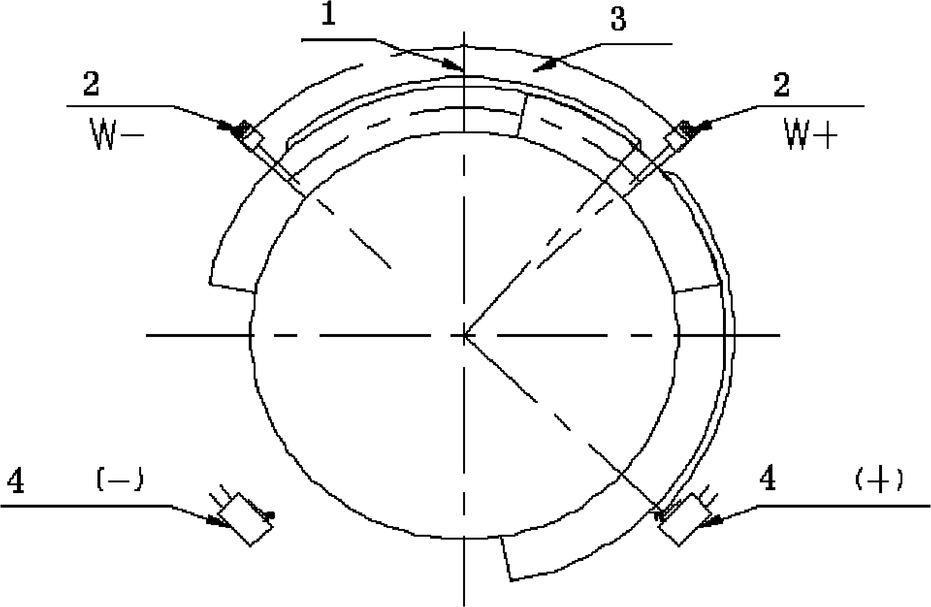
[0030] 2. On both sides of the zero point 1 (in the travel direction), install a mechanical switch (or photoelectric switch, etc.) 2 symmetrically, denoted as W+, W-, and the angle between the installation position and the zero point is ±46 degrees;

[0031] 3. On the rotating body of the incremental sensor, install a mechanical stopper 3, the stopper is centered on the zero point, and the axial angle of the stopper is 102 degrees. When the photoelectric switch is blocked by the block, its signal is 1, and the signal is 0 when it is not blocked;

[0032] 4. When crossing zero, the electr...

Embodiment 2

[0038] Embodiment 2: The azimuth axis automatic zeroing system of the 400mm horizon telescope has a rotation range of 360 degrees.

[0039] The processing flow is as follows:

[0040] 1. The position detection device of the azimuth axis is an incremental laser grating code disc, and its zero-position engraved line is adjusted to the middle position of the running stroke during installation;

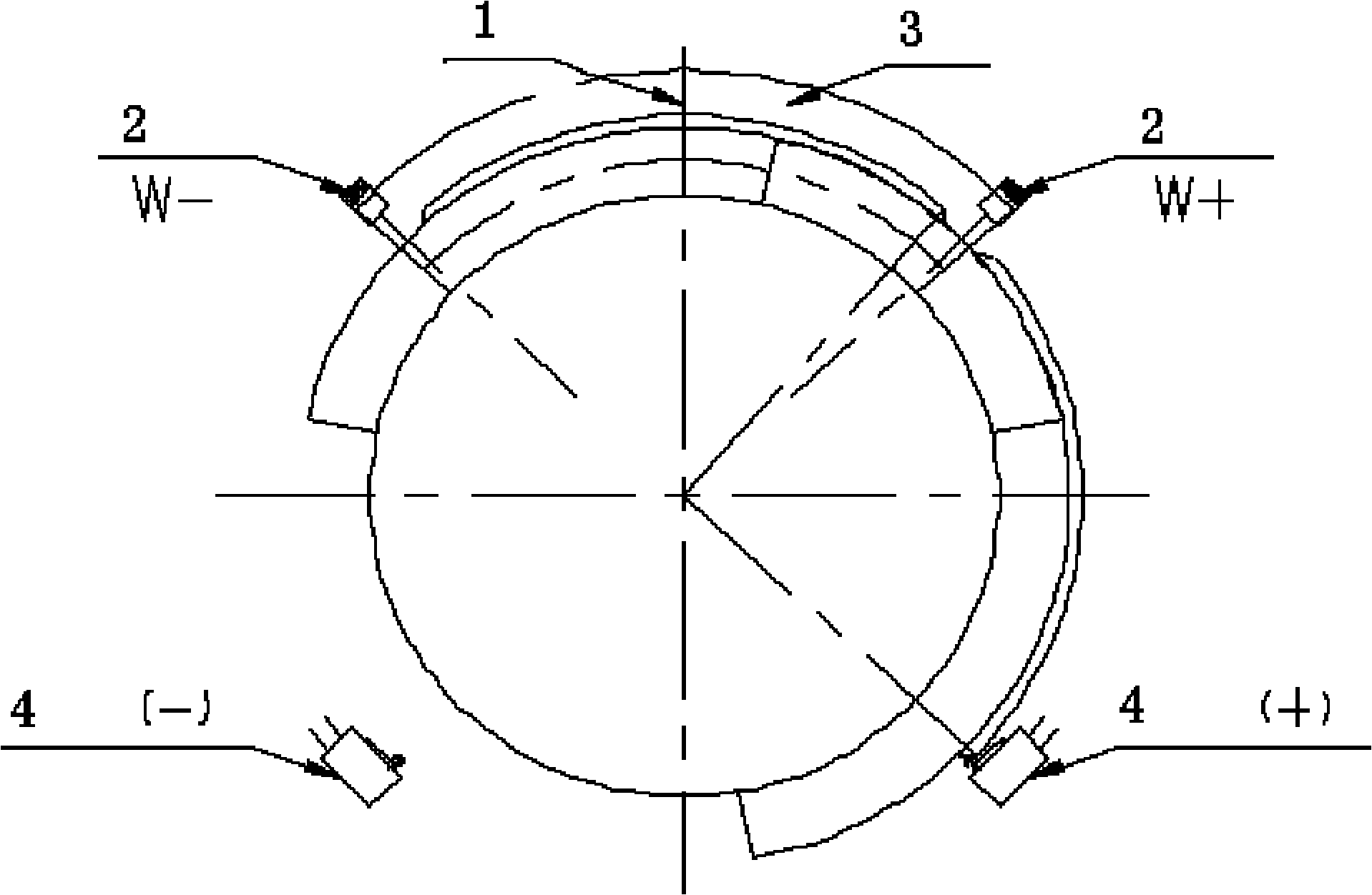
[0041] 2. On both sides of the zero point (in the travel direction), symmetrically install a mechanical switch (or photoelectric switch, etc.), which is recorded as W+, W-, and the angle between the installation position and the zero point is ±92 degrees;

[0042] 3. Install a mechanical baffle on the rotating body, the baffle is centered on the zero point, and the axial angle of the baffle is 192 degrees. When the photoelectric switch is blocked by the block, its signal is 1, and the signal is 0 when it is not blocked;

[0043] 4. When crossing zero, the electronic control system conti...


PUM


Abstract

The invention relates to an automatic zeroing method and automatic zeroing equipment for an incremental sensor. The method comprises the following steps of: (1) arranging a zero point detection device at the middle position of a motion stroke; (2) symmetrically arranging switches W+ and W- in the stroke directions on the two sides of a zero point; (3) arranging a zero point-centered baffle sheet on a rotating body, wherein a signal is 1 when a photoelectric switch is baffled by the baffle sheet, while the signal is 0 when the photoelectric switch is not baffled by the baffle sheet; (4) continuously detecting the values of the W+ and W- during zero-crossing by an electric control system; (5) continuously checking a zero point signal, zeroing the reading of an angular sensor when the zero point signal takes effect, or automatically zeroing the reading of the angular sensor by hardware when the zero point signal takes effect; and (6) indicating that zeroing fails if detecting that the states of the W+ and W- are changed into 01 from 10, or 10 from 01 but not detecting the zero point signal during the zero-crossing, and zeroing again. The method and the equipment overcome the defects of the prior art and can quickly judge the zeroing direction, shorten a redundancy stroke and realize high-efficiency automatic zeroing.

Description

technical field [0001] The invention belongs to the field of electromechanical integration instruments and equipment, and in particular relates to a method for automatic zero return of an incremental sensor and equipment thereof. Background technique [0002] The electromechanical system of position closed-loop control generally uses some kind of angle detection device (such as shaft angle encoder, etc.) to measure the current rotation angle of the moving parts. The shaft angle detection device can be divided into two categories: absolute sensor and incremental sensor. The data measured by the absolute sensor is always the current rotation angle of the moving body, and does not need a reference to the zero point; while the data measured by the incremental sensor is the angle of the moving body from the zero point. When the system is powered off or the measurement result is due to some After the cause is wrong, it must be turned back to the zero point (it can be judged by the...

Claims


Application Information

Patent Timeline
Patent Type & Authority Applications(China)
IPC IPC(8): G01D3/06
Inventor 陈伟民吴金虎朱庆生
Owner NANJING NAIERSI PHOTOELECTRIC INSTR
Why Eureka
Try Eureka