Pipe type hydraulic fluid muffler

A technology of hydraulic fluid and muffler, which is applied in the direction of pipe components, pipes/pipe joints/fittings, mechanical equipment, etc., can solve the problems of hydraulic system noise, etc., and achieve the effect of reducing noise and vibration, novel structure, and reducing noise and vibration

Active Publication Date: 2011-02-16
TAIYUAN HEAVY IND
View PDF6 Cites 6 Cited by
  • Summary
  • Abstract
  • Description
  • Claims
  • Application Information

AI Technical Summary

Problems solved by technology

[0003] The purpose of the present invention is to overcome the shortcomings of the prior art and

Method used


Image

  • Pipe type hydraulic fluid muffler
  • Pipe type hydraulic fluid muffler
  • Pipe type hydraulic fluid muffler

Examples


Embodiment Construction

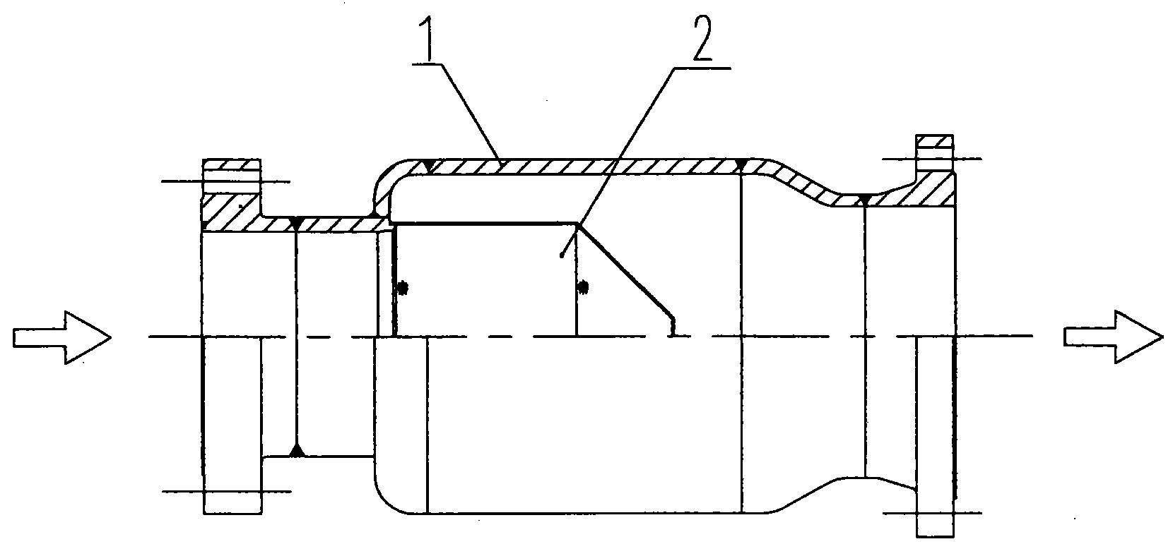
[0017] Such as figure 1 As shown, a pipe-type hydraulic fluid muffler is composed of a muffler shell 1 and a muffler main body 2 , and the muffler main body 2 is welded and installed in the muffler shell 1 . It is worth noting that in the manufacturing process, the muffler main body 2 must be welded to the connecting pipe 4 of the muffler housing 1 before welding other parts of the muffler housing 1 can be completed.

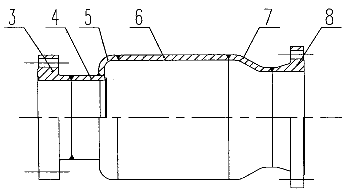
[0018] Such as figure 2 As shown, the muffler shell 1 is composed of an inlet flange 3, a connecting pipe 4, an arc joint 5, a cylinder body 6, a variable diameter joint 7 and an outlet flange 8, and these parts are connected together by welding to form the muffler shell 1 , its inner cavity is a smooth transition without sharp corners, and the inlet flange 3 and outlet flange 8 are used to connect the hydraulic pipes at both ends in series.

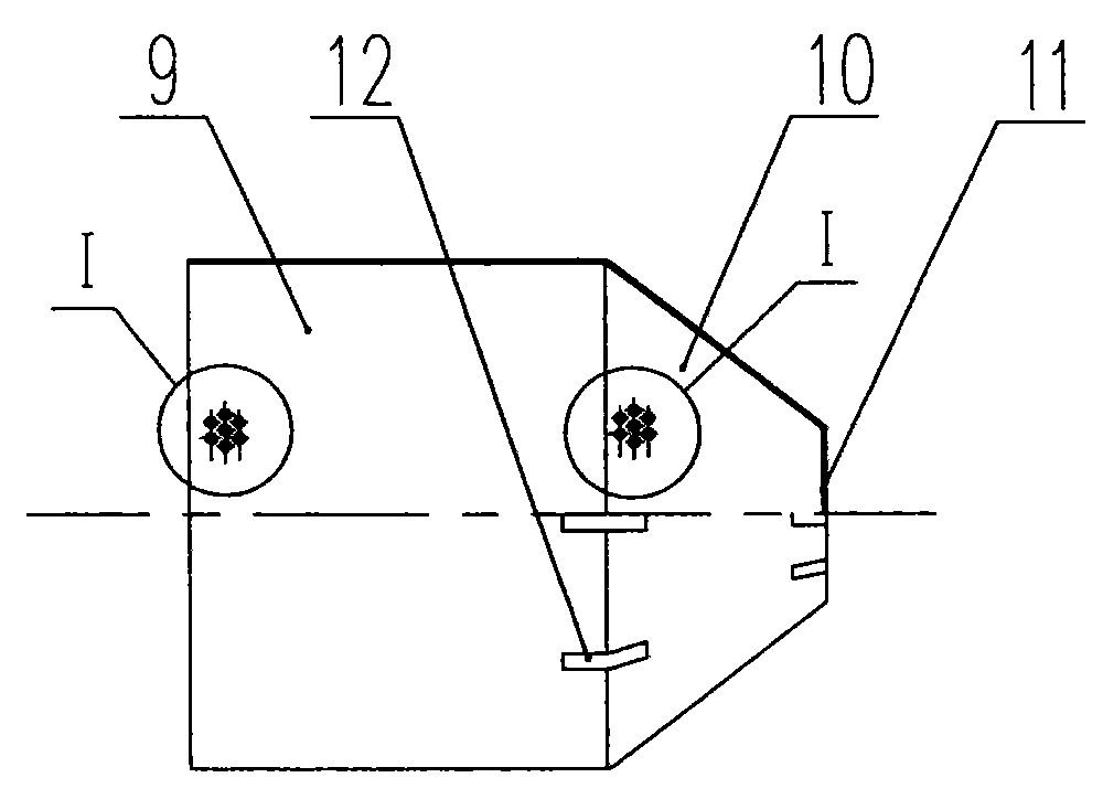
[0019] Such as image 3 As shown, the muffler main body 2 is composed of a porous cylinder 9 , a porous conical cyli...


PUM

PropertyMeasurementUnit
Hole diameteraaaaaaaaaa

Abstract

The invention relates to a pipe type hydraulic fluid muffler, relating to the hydraulic pipes of hydraulic equipment and being used for solving the noise problem of the hydraulic pipes. The pipe type hydraulic fluid muffler consists a muffler shell and a muffler main body arranged in the muffler shell, wherein an inlet flange, a connecting pipe, an arc joint, a cylinder, a reducer union and an outlet flange of the muffler shell are welded together in sequence, and the inlet flange and the outlet flange are respectively connected in series with the hydraulic pipes at the two ends; and the muffler main body consists of a porous cylinder, a porous cone, a baffle and connecting reinforced plates, wherein the porous cylinder is connected with the big end of the porous cone, the small end of the porous cone is sealed with the baffle, and the connecting reinforced plates are respectively welded between the porous cylinder and the porous cone and between the porous cone and the baffle. Since the pipe type hydraulic fluid muffler is connected in series with the hydraulic pipes, the noise and vibration of a hydraulic system can be lowered and reduced effectively. The pipe type hydraulic fluid muffler has the advantages of novel and simple structure, low cost, good practicality, and the like.

Description

technical field [0001] The invention relates to hydraulic pipelines of hydraulic equipment, in particular to mufflers for pipelines with large fluctuations in liquid pressure and flow. Background technique [0002] In the hydraulic system of hydraulic equipment, hydraulic pipelines are essential, and the liquid flows in the hydraulic pipelines to drive the operation of hydraulic equipment. When the liquid flows in the hydraulic pipeline, due to the friction between the liquid and the inner wall of the pipeline and the mutual friction between the liquids, or due to the sudden change of the pressure of the liquid, sound will be produced. When the sound exceeds 70 decibels, it will become noise, which makes people sound very uncomfortable. Comfortable, even disturbing, noise as pollution has been increasingly valued by people. Especially in recent years, with the development of hydraulic technology towards high speed, high pressure, high frequency response and high power, the ...

Claims


Application Information

Patent Timeline
IPC IPC(8): F16L55/033
Inventor 王玲玲解文科
Owner TAIYUAN HEAVY IND
Why Eureka
Try Eureka