Novel axial fatigue tester

A fatigue testing machine, axial technology, applied in the direction of applying repetitive force/pulsation force to test the strength of materials, etc., can solve problems such as complex structure and single function

Inactive Publication Date: 2011-02-16
黄衍国
View PDF6 Cites 11 Cited by
  • Summary
  • Abstract
  • Description
  • Claims
  • Application Information

AI Technical Summary

Problems solved by technology

The axial fatigue testing machine must be used to carry out the fatigue test on the product to ensure the performance of the product. However, the existing axial fatigue testing machine only simply performs a single function test of tension or compression on the thrust rod workpiece, which has a single function and a complex structure.

Method used


Image

  • Novel axial fatigue tester
  • Novel axial fatigue tester
  • Novel axial fatigue tester

Examples


Embodiment Construction

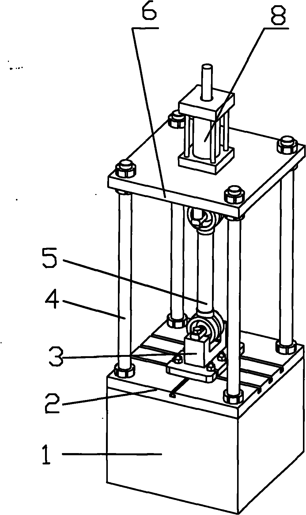
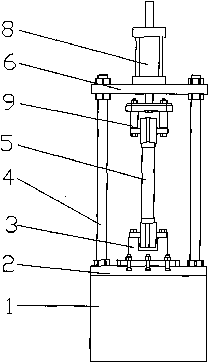
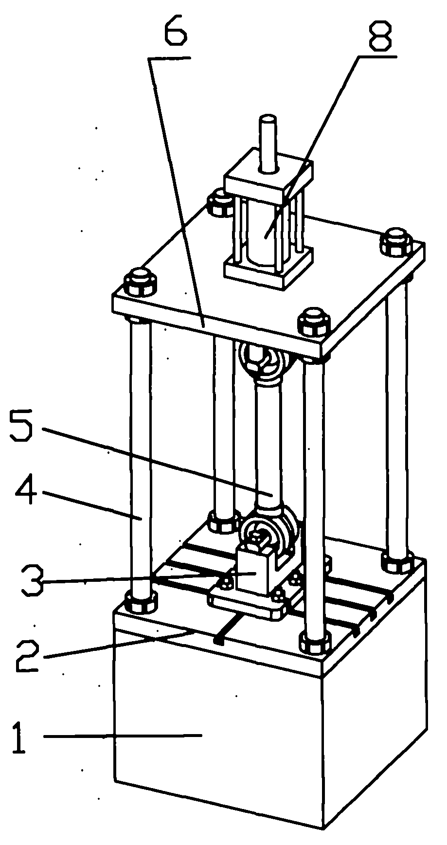
[0010] Such as figure 1 , figure 2 As shown, a new axial fatigue testing machine includes a workbench 2, a lower U-shaped connecting seat 3 arranged in the middle of the workbench 2, an upper connecting plate 6 arranged above the workbench 2, and an upper connecting plate 6 arranged between the workbench 1 and the upper The support column 4 between the connecting plates 6, the upper U-shaped connecting seat 9 located in the middle of the lower end surface of the upper connecting plate 6, the main oil cylinder 8 located on the upper end surface of the upper connecting plate 6, the piston rod lower end of the main oil cylinder 8 and the Upper U-shaped connecting seat 9 is connected into one. The workbench 2 is fixed on the base 1, the support columns 4 are provided with four, and are arranged at the four corners of the upper connecting plate 6, and the lower U-shaped connecting seat 3 and the upper U-shaped connecting seat 9 are installed with Thrust rod part 5. During the t...


PUM


Abstract

The invention relates to the field of automobile accessories, in particular to a novel axial fatigue tester. The novel axial fatigue tester comprises a workbench, a lower U-shaped connection base, an upper connection board, a support pole, an upper U-shaped connection base and a main oil cylinder, wherein the lower U-shaped connection base is arranged in the middle of the workbench; the upper connection board is arranged above the workbench; the support pole is arranged between the workbench and the upper connection board; the upper U-shaped connection base is arranged in the middle of the lower end face of the upper connection board; and the main oil cylinder is arranged on the upper end face of the upper connection board, and the lower end of a piston rod of the main oil cylinder is integrally connected with the upper U-shaped connection base. Due to the structure, the stretching and compression of a thrust rod can be realized, so that sinusoidal wave is realized, and the tester is convenient to use and simple in structure.

Description

technical field [0001] The invention relates to the field of auto parts, in particular to a novel axial fatigue testing machine. Background technique [0002] Automotive thrust rods are widely used in dual rear axle balance suspension and air suspension trucks and passenger cars to maintain the relative position between the two axles or between the axle and the frame, and to transmit the longitudinal and lateral forces of the car. Forces and moments in other directions can also be transmitted. The thrust rod of the car is mainly composed of a ball head and a sleeve in the axial direction through several corrugated bites to support the truck and passenger car, and is used to maintain a large axial force between the two axles or between the axle and the car. It is required to be able to withstand a certain torque T and tension F. The axial fatigue testing machine must be used to carry out the fatigue test on the product to ensure the performance of the product. However, the ...

Claims


Application Information

Patent Timeline
Patent Type & Authority Applications(China)
IPC IPC(8): G01N3/36
Inventor 黄衍国
Owner 黄衍国
Why Eureka
Try Eureka