Glass tube heating and firing device for manufacturing high borosilicate glass container

A high borosilicate glass and container manufacturing technology, applied in glass manufacturing equipment, manufacturing tools, glass molding, etc., can solve problems such as low operating efficiency, achieve adjustment effects, improve heating and firing effects, and prompt adjustment flexibility Effect

Inactive Publication Date: 2020-08-07
新沂市弘扬果谷工艺品有限公司
View PDF6 Cites 8 Cited by
  • Summary
  • Abstract
  • Description
  • Claims
  • Application Information

AI Technical Summary

Problems solved by technology

Although the device can be used for firing glass instruments, it cannot be adjusted flexibly during the firing process of glass tubes, resulting in low firing operation efficiency. For this reason, a high borosilicate glass container manufacturing device is now provided. Glass tube heating and firing device to solve the above technical problems

Method used


Image

  • Glass tube heating and firing device for manufacturing high borosilicate glass container
  • Glass tube heating and firing device for manufacturing high borosilicate glass container
  • Glass tube heating and firing device for manufacturing high borosilicate glass container

Examples


Embodiment 1

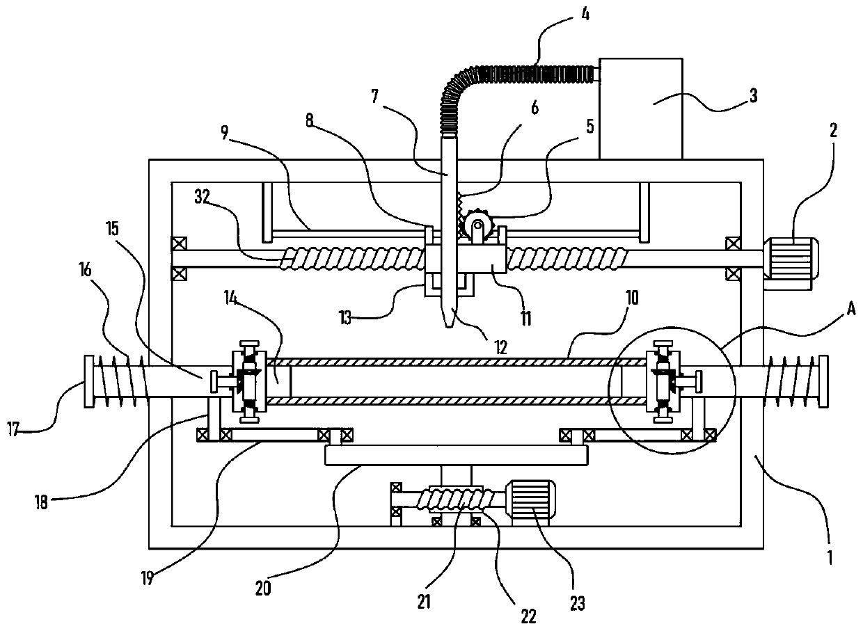
[0023] See Figure 1-4 , A glass tube heating and firing device for the manufacture of high borosilicate glass containers, comprising a fixing frame 1, a gas tank 3 is fixed on the fixing frame 1, and the fixing frame 1 is provided with a translation mechanism driven by a motor I2. A screw sleeve block 11 is provided. A limit frame 13 is fixed at the bottom of the screw sleeve block 11. A nozzle 12 connected to the gas tank 3 is slidably installed on the limit frame 13, and the screw sleeve block 11 is provided with a nozzle 12 for driving Vertically adjustable lifting mechanism, the fixed frame 1 is fixed with a motor II23, two symmetrically arranged guide rods 15 are slidably mounted on the fixed frame 1, and the guide rods 15 are fixed on the ends of the glass tube 10 A locking mechanism, a driving mechanism for driving the guide rod 15 to slide laterally is drivingly connected to the motor II23.

[0024] The locking mechanism of the device locks and fixes the two ends of the...

Embodiment 2

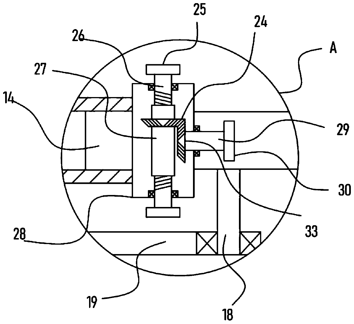
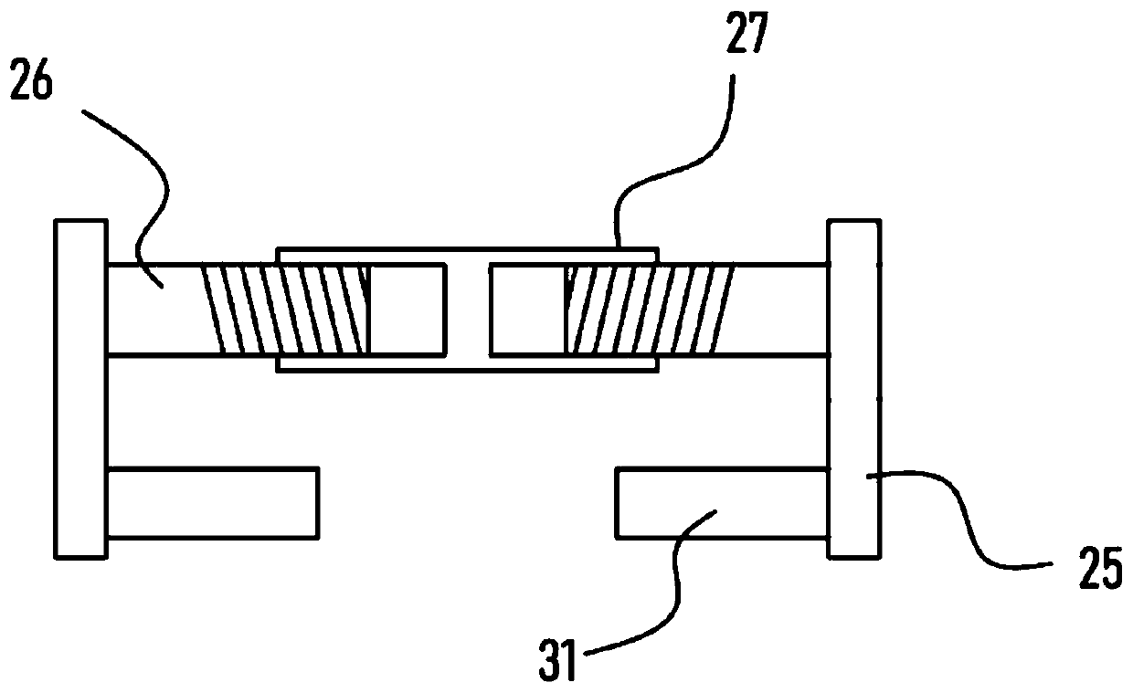
[0029] On the basis of embodiment 1, in addition, the locking mechanism of the device includes a clamping sleeve block 28 fixed at the end of the guide rod 15, and a clamping block 14 is fixed on the clamping sleeve block 28, the clamping sleeve block 28 A threaded sleeve 27 is installed on the upper rotation. Two screws 26 with opposite screw threads are connected in the threaded sleeve 27. The end of the screw 26 is fixed with a connecting plate 25, and the connecting plate 25 is fixed with a sliding block inserted into the clamping sleeve. 28, the locking mechanism also includes a rotating shaft 29 rotatably mounted on the clamping sleeve 28, a bevel gear II33 is coaxially fixed on the rotating shaft 29, and a bevel gear II33 is meshed and connected with a sleeve and fixed on the thread Bevel gear I24 on sleeve 27.

[0030] The two ends of the glass tube 10 are inserted into the clamping sleeve block 28, the set block 14 enters into the glass tube 10 for support, and the screw...


PUM


Abstract

The invention discloses a glass tube heating and firing device for manufacturing a high borosilicate glass container, and relates to the technical field of high borosilicate glass tube processing; andthe device comprises a fixing frame, a nozzle communicated with a gas tank is slidably mounted on a limiting frame, a locking mechanism used for clamping the end of a glass tube is fixed on a guide rod, and a motor II is in driving connection with a driving mechanism used for driving the guide rod to slide transversely. According to the invention, the end part of the glass tube can be clamped andfixed through the arranged locking mechanism; the arranged driving mechanism can drive the two guide rods to move back to back, so stretching of the glass tube is realized; the stretching plastic part of the glass tube is heated and fired by the flame sprayed by the arranged nozzle; the transverse position of the glass tube corresponding to the nozzle can be adjusted through the arranged translation mechanism, so the adjusting flexibility in the firing process is greatly promoted, meanwhile, the distance between flame and the glass tube can be adjusted through the lifting mechanism, the firing temperature adjusting effect is achieved, and the heating firing effect of the glass tube is greatly improved.

Description

Technical field [0001] The invention relates to the technical field of high borosilicate glass tube processing, in particular to a glass tube heating and firing device for manufacturing high borosilicate glass containers. Background technique [0002] High borosilicate glass is made by using the properties of glass to conduct electricity under high temperature conditions, by heating inside the glass to achieve glass melting, and processed by advanced production technology. Silicon oxide in glass tube> 78%, boron oxide> 10%, the content of silicon and boron is very high. The raw materials for making high borosilicate glass include main raw materials and auxiliary raw materials. The former refers to the introduction of glass to form network structure oxides, intermediate oxides and external oxides. It can accelerate the glass melting, or make it obtain certain necessary properties. During the cutting process of the high borosilicate glass tube, it needs to be clamped and fixe...

Claims


Application Information

Patent Timeline
Patent Type & Authority Applications(China)
IPC IPC(8): C03B23/043C03B23/045C03B23/047
CPCC03B23/043C03B23/045C03B23/047
Inventor 黄建
Owner 新沂市弘扬果谷工艺品有限公司
Why Eureka
Try Eureka